Page 486 of 586
5-61
CHASREAR SHOCK ABSORBER
EC583000
REMOVAL POINTS
EC583320
Bearing
1. Remove:
9Stopper ring (upper bearing) 1
NOTE:
Press in the bearing while pressing its outer race
and remove the stopper ring.
2. Remove:
9Upper bearing 1
NOTE:
Remove the bearing by pressing its outer race.
EC584000
INSPECTION
EC584110
Rear shock absorber
1. Inspect:
9Damper rod 1
Bends/Damage �Replace absorber
assembly.
9Shock absorber 2
Oil leaks �Replace absorber assembly.
Gas leaks �Replace absorber assembly.
9Spring 3
Damage �Replace spring.
Fatigue �Replace spring.
Move spring up and down.
9Spring guide 4
Wear/Damage �Replace spring guide.
9Bearing 5
Free play exists/Unsmooth revolution/
Rust �Replace. 3. Remove:
9Lower bearing 1
NOTE:
Remove the bearing by pressing its outer race.
5UP-9-30-5DN 5/24/02 6:04 PM Page 22
Page 494 of 586
6-1
ELECTRICAL COMPONENTS AND WIRING DIAGRAMELEC
EC600000
ELECTRICAL
EC610000
ELECTRICAL COMPONENTS AND WIRING DIAGRAM
EC611000
ELECTRICAL COMPONENTS
1CDI unit
2“ENGINE STOP” button
3Ignition coil
4TPS (throttle position sensor)
5Solenoid valve
6CDI magneto
7Spark plug
EC612000
WIRING DIAGRAM
COLOR CODE
B...................Black
L ...................Blue
O ..................Orange
R ..................Red
Y...................Yellow
B/L................Black/Blue
B/R ...............Black/Red
B/W ..............Black/White
G/L ..............Green/Blue
G/W ..............Green/White
W/L...............White/Blue
W/R ..............White/Red
L
Y
B/LYL
B/LY LL
Y
B
B/W
B B/W
B
R
BB
RR
RR
R
B
B/R
G/L
G/W
W/R
W/L W/L B/R
G/L
W/R
B G/W G/L B/R W/L
G/W B W/R
O
B G/W G/L
Y B/L
L
W/R
W/L
B
R
B/R
B/W
O G/L
B/L
L
W/L
B
R
B/R
B/WG/W
Y
W/R
OB/L
5UP-9-30-6 5/24/02 5:35 PM Page 2
Page 496 of 586
6-2
IGNITION SYSTEMELEC
EC620000
IGNITION SYSTEM
EC621003
INSPECTION STEPS
Use the following steps for checking the possibility of the malfunctioning engine being attributable to
ignition system failure and for checking the spark plug which will not spark.
*Clean or replace
spark plug.
Primary coil
Secondary coil
Repair or replace.
Spark
Check entire ignition
system for connection.
Spark gap test
No good
No good
No good
No good
No good
No good No Spark
Check “ENGINE STOP”
button.
Pick-up coil
Source coil
Check ignition coil.
Check CDI magneto.
Replace CDI unit.
Replace.
Replace.
Replace.
Replace.
Replace.
*marked: Only when the ignition checker is used.
NOTE:
9Remove the following parts before inspection.
1) Seat
2) Fuel tank
9Use the following special tools in this inspection.
Dynamic spark tester:
YM-34487
Ignition checker:
90890-06754Pocket tester:
YU-3112-C/90890-03112
OK
OK
OK
OKReplace.
Check spark plug cap.No good
OK
5UP-9-30-6 5/24/02 5:35 PM Page 4
Page 502 of 586
6-4
IGNITION SYSTEMELEC
EC626003
IGNITION COIL INSPECTION
1. Inspect:
9Primary coil resistance
Out of specification �Replace.
2. Inspect:
9Secondary coil resistance
Out of specification �Replace.
NOTE:
9Remove the spark plug cap by turning it coun-
terclockwise and inspect.
9Install the spark plug cap by turning it clock-
wise until it is tight.
Tester (+) lead�Orange lead 1
Tester (–) lead
�Black lead 2
Tester (+) lead�Spark plug lead 1
Tester (–) lead
�Orange lead 2
Primary coil Tester selector
resistance position
0.20~0.30Ωat
Ω× 1
20°C (68°F)
Secondary coil Tester selector
resistance position
9.5~14.3kΩat
kΩ× 1
20°C (68°F)
5UP-9-30-6 5/24/02 5:36 PM Page 10
Page 504 of 586
6-5
IGNITION SYSTEMELEC
2. Inspect:
9Source coil 1 resistance
Out of specification �Replace.
Tester (+) lead�Black/Red lead 1
Tester (–) lead
�Blacklead 2
Source coil 1 Tester selector
resistance position
720~1,080Ωat
Ω× 100
20°C (68°F)
EC62B000
SPARK PLUG CAP INSPECTION
1.Inspect:
9Spark plug cap
Loose connection �Tighten.
Deteriorated/Damaged �Replace.
9Spark plug cap resistance
Out of specification �Replace.
Tester (+) lead�Spark plug lead terminal1
Tester (–) lead
�Spark plug terminal2
Spark plug cap Tester selector
resistance position
4~6kΩat
kΩ× 1
20°C (68°F)
EC627011
CDI MAGNETO INSPECTION
1. Inspect:
9Pick-up coil resistance
Out of specification �Replace.
Tester (+) lead�White/Red lead 1
Tester (–) lead
�White/Blue lead 2
Pick–up coil Tester selector
resistance position
248~372Ωat
Ω× 100
20°C (68°F)
5UP-9-30-6 5/24/02 5:36 PM Page 12
Page 506 of 586
6-6
IGNITION SYSTEMELEC
3. Inspect:
9Source coil 2 resistance
Out of specification �Replace.
EC628000
CDI UNIT INSPECTION
Check all electrical components. If no fault is
found, replace the CDI unit. Then check the
electrical components again.
Tester (+) lead�Green/Blue lead 1
Tester (–) lead
�Green/White lead 2
Source coil 2 Tester selector
resistance position
44~66Ωat
Ω× 10
20°C (68°F)
5UP-9-30-6 5/24/02 5:36 PM Page 14
Page 508 of 586
6-7
SOLENOID VALVE SYSTEMELEC
Check solenoid
valve operation.
Solenoid valve
coil
No good
No good
Check each couplers and
wire connection.
Check solenoid valve.
Repair or replace.
Replace.
Replace.
OK
OK
OKSource coil
No goodReplace.* Check CDI magneto.
Replace CDI unit.
No good
EC650001
SOLENOID VALVE SYSTEM
EC651032
INSPECTION STEPS
If the solenoid valve will not operate, use the following inspection steps.
* marked: Refer to "IGNITION SYSTEM" section.
NOTE:
9Remove the following parts before inspection.
1) Seat
2) Fuel tank
9Use l2V battery in this inspection.
9Use the following special tools in this inspection.
Pocket tester:
YU-3112-C/90890-03112
5UP-9-30-6 5/24/02 5:36 PM Page 16
Page 512 of 586
6-8
SOLENOID VALVE SYSTEMELEC
EC624000
COUPLERS AND LEADS CONNECTION
INSPECTION
1. Check:
9Couplers and leads connection
Rust/ Dust/ Looseness/Short-circuit �
Repair or replace.
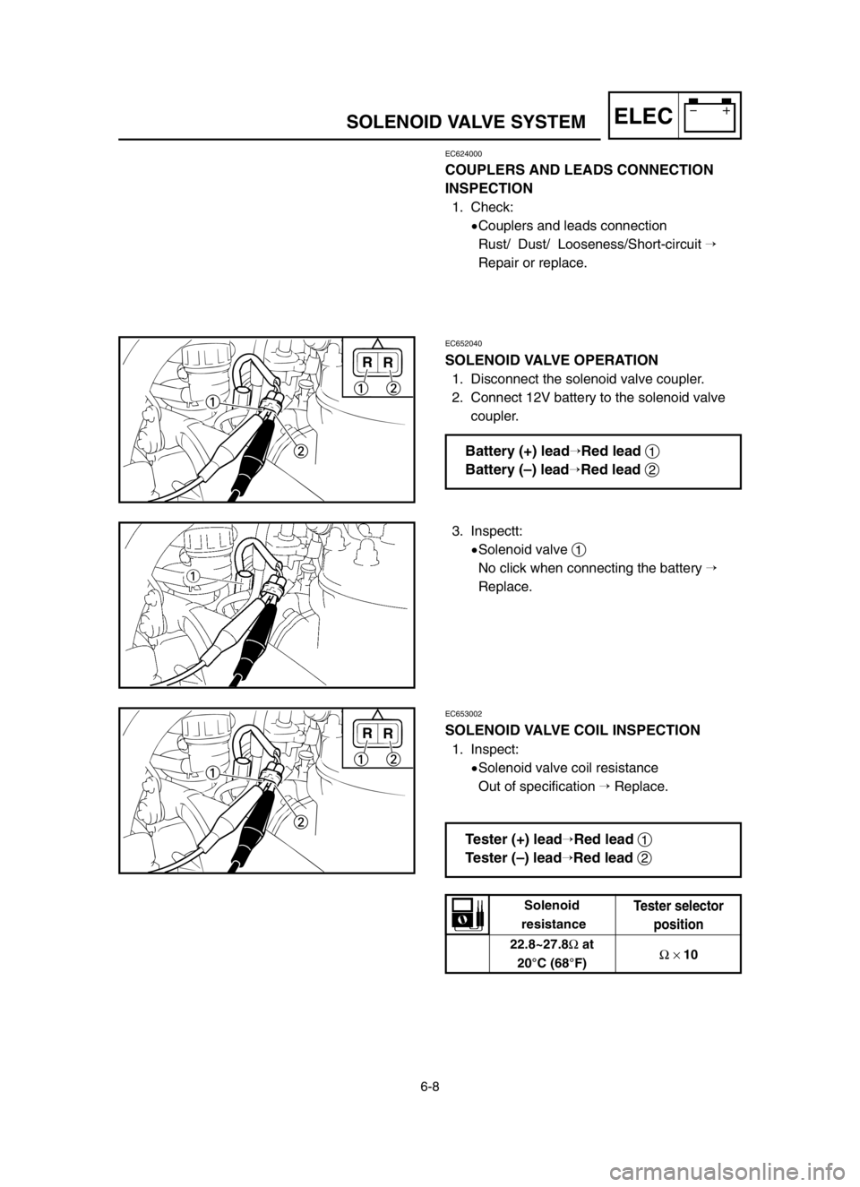
EC652040
SOLENOID VALVE OPERATION
1. Disconnect the solenoid valve coupler.
2. Connect 12V battery to the solenoid valve
coupler.
3. Inspectt:
9Solenoid valve
1
No click when connecting the battery �
Replace.
EC653002
SOLENOID VALVE COIL INSPECTION
1. Inspect:
9Solenoid valve coil resistance
Out of specification �Replace.
R
1
2
12R
R
1
2
12R
Tester (+) lead�Red lead 1
Tester (–) lead
�Red lead 2
22.8~27.8Ωat
20°C (68°F) Solenoid
resistance
Tester selector
position
Ω× 10
Battery (+) lead�Red lead 1
Battery (–) lead
�Red lead 2
5UP-9-30-6 5/24/02 5:36 PM Page 20
 5-61
CHASREAR SHOCK ABSORBER
EC583000
REMOVAL POINTS
EC583320
Bearing
1. Remove:
9Stopper ring (upper bearing) 1
NOTE:
Press in the bearing while pressing its outer race
and remove the stopper ring.
2")
 6-1
ELECTRICAL COMPONENTS AND WIRING DIAGRAMELEC
EC600000
ELECTRICAL
EC610000
ELECTRICAL COMPONENTS AND WIRING DIAGRAM
EC611000
ELECTRICAL COMPONENTS
1CDI unit
2“ENGINE STOP” button
3Ignition coil")
 6-2
IGNITION SYSTEMELEC
EC620000
IGNITION SYSTEM
EC621003
INSPECTION STEPS
Use the following steps for checking the possibility of the malfunctioning engine being attributable to
ignition system failu")


 6-7
SOLENOID VALVE SYSTEMELEC
Check solenoid
valve operation.
Solenoid valve
coil
No good
No good
Check each couplers and
wire connection.
Check solenoid valve.
Repair or replace.
Replace.
Replace.
OK")