Page 32 of 754
 1 - 4
GEN
INFO
IMPORTANT INFORMATION
EC132000
ALL REPLACEMENT PARTS
1. We recommend to use Yamaha genuine
parts for all replacements. Use oil and/or
grease recommended by Yamaha for
assembly and adjus")
1 - 4
GEN
INFO
IMPORTANT INFORMATION
EC132000
ALL REPLACEMENT PARTS
1. We recommend to use Yamaha genuine
parts for all replacements. Use oil and/or
grease recommended by Yamaha for
assembly and adjustment.
EC133000
GASKETS, OIL SEALS AND O-RINGS
1. All gaskets, oil seals, and O-rings should
be replaced when an engine is over-
hauled. All gasket surfaces, oil seal lips,
and O-rings must be cleaned.
2. Properly oil all mating parts and bearings
during reassembly. Apply grease to the
oil seal lips.
EC134000
LOCK WASHERS/PLATES AND COTTER
PINS
1. All lock washers/plates 1 and cotter pins
must be replaced when they are
removed. Lock tab(s) should be bent
along the bolt or nut flat(s) after the bolt
or nut has been properly tightened.
EC135001
BEARINGS AND OIL SEALS
1. Install the bearing(s) 1 and oil seal(s) 2
with their manufacturer’s marks or num-
bers facing outward. (In other words, the
stamped letters must be on the side
exposed to view.) When installing oil
seal(s), apply a light coating of light-
weight lithium base grease to the seal
lip(s). Oil the bearings liberally when
installing.
CAUTION:
Do not use compressed air to spin the
bearings dry. This causes damage to the
bearing surfaces.
Page 72 of 754
 1 - 20
GEN
INFO
CLEANING AND STORAGE
EC1B0000
CLEANING AND STORAGE
EC1B1000
CLEANING
Frequent cleaning of your machine will
enhance its appearance, maintain good over-
all performance, and extend the")
1 - 20
GEN
INFO
CLEANING AND STORAGE
EC1B0000
CLEANING AND STORAGE
EC1B1000
CLEANING
Frequent cleaning of your machine will
enhance its appearance, maintain good over-
all performance, and extend the life of many
components.
1. Before washing the machine, block off
the end of the exhaust pipe to prevent
water from entering. A plastic bag
secured with a rubber band may be used
for this purpose.
2. If the engine is excessively greasy, apply
some degreaser to it with a paint brush.
Do not apply degreaser to the chain,
sprockets, or wheel axles.
3. Rinse the dirt and degreaser off with a
garden hose; use only enough pressure
to do the job.
CAUTION:
Excessive hose pressure may cause water
seepage and contamination of wheel bear-
ings, front forks, brakes and transmission
seals. Many expensive repair bills have
resulted from improper high pressure
detergent applications such as those avail-
able in coin-operated car washers.
4. After the majority of the dirt has been
hosed off, wash all surfaces with warm
water and a mild detergent. Use an old
toothbrush to clean hard-to-reach places.
5. Rinse the machine off immediately with
clean water, and dry all surfaces with a
soft towel or cloth.
6. Immediately after washing, remove
excess water from the chain with a paper
towel and lubricate the chain to prevent
rust.
7. Clean the seat with a vinyl upholstery
cleaner to keep the cover pliable and
glossy.
Page 190 of 754
3 - 6
INSP
ADJ
COOLANT REPLACEMENT
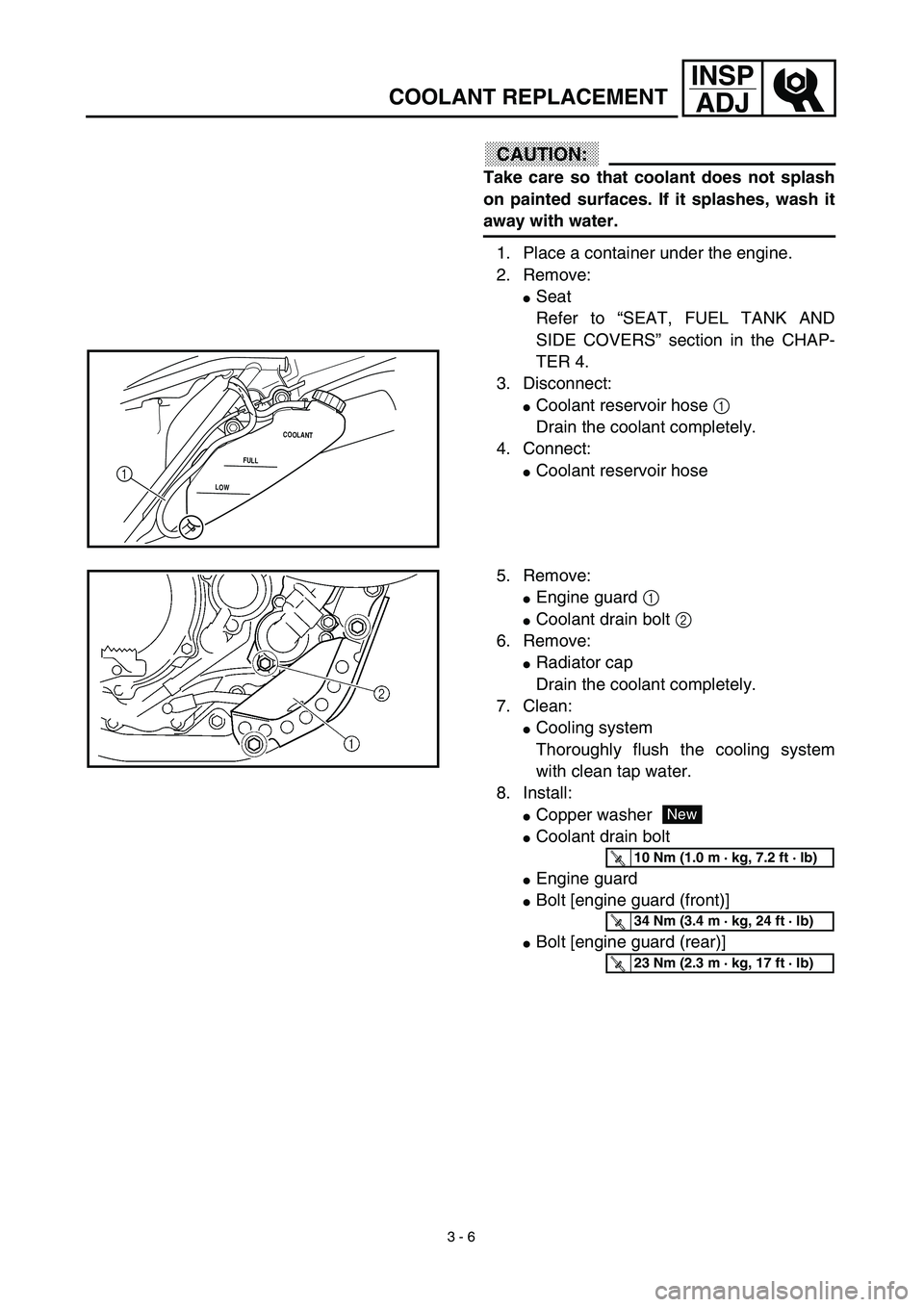
CAUTION:
Take care so that coolant does not splash
on painted surfaces. If it splashes, wash it
away with water.
1. Place a container under the engine.
2. Remove:
�Seat
Refer to “SEAT, FUEL TANK AND
SIDE COVERS” section in the CHAP-
TER 4.
3. Disconnect:
�Coolant reservoir hose 1
Drain the coolant completely.
4. Connect:
�Coolant reservoir hoseLOWFULLCOOLANT1
5. Remove:
�Engine guard 1
�Coolant drain bolt 2
6. Remove:
�Radiator cap
Drain the coolant completely.
7. Clean:
�Cooling system
Thoroughly flush the cooling system
with clean tap water.
8. Install:
�Copper washer
�Coolant drain bolt
�Engine guard
�Bolt [engine guard (front)]
�Bolt [engine guard (rear)]
New
T R..10 Nm (1.0 m · kg, 7.2 ft · lb)
T R..34 Nm (3.4 m · kg, 24 ft · lb)
T R..23 Nm (2.3 m · kg, 17 ft · lb)
Page 212 of 754
 3 - 17
INSP
ADJ
ENGINE OIL REPLACEMENT
6. If the oil filter is to be replaced during this
oil change, remove the following parts
and reinstall them.
7. Install:
�Plain washer 1
�Oil strainer (frame)")
3 - 17
INSP
ADJ
ENGINE OIL REPLACEMENT
6. If the oil filter is to be replaced during this
oil change, remove the following parts
and reinstall them.
7. Install:
�Plain washer 1
�Oil strainer (frame) 2
�Engine oil hose 3
�Bolt (engine oil hose) 4
�Engine oil hose clamp 5
�Engine skid plate
8. Install:
�Gaskets
�Oil filter drain bolt
�Drain bolt (crankcase rear)
�Drain bolt (crankcase left)
�Drain bolt (frame)
9. Fill:
�Crankcase
10. Install:
�Oil filler plug
11. Inspect:
�Engine (for oil leaks)
�Oil level
Refer to “ENGINE OIL LEVEL INSPEC-
TION”. Replacement steps:
�Remove the exhaust pipe.
�Remove the oil filter cover 1 and oil filter
element 2.
�Check the O-rings 3, if cracked or dam-
aged, replace them with a new one.
�Install the oil filter element and oil filter
cover.
T R..
Oil filter cover:
10 Nm (1.0 m • kg, 7.2 ft • lb)
Oil quantity:
Total amount:
1.2 L (1.06 Imp qt, 1.27 US qt)
Periodic oil change:
1.0 L (0.88 Imp qt, 1.06 US qt)
With oil filter replacement:
1.1 L (0.97 Imp qt, 1.16 US qt)
New
T R..90 Nm (9.0 m · kg, 65 ft · lb)
T R..10 Nm (1.0 m · kg, 7.2 ft · lb)
T R..2 Nm (0.2 m · kg, 1.4 ft · lb)
New
T R..10 Nm (1.0 m · kg, 7.2 ft · lb)
T R..20 Nm (2.0 m · kg, 14 ft · lb)
T R..10 Nm (1.0 m · kg, 7.2 ft · lb)
T R..23 Nm (2.3 m · kg, 17 ft · lb)
Page 272 of 754
 3 - 46
INSP
ADJ
STEERING HEAD INSPECTION AND ADJUSTMENT
�Tighten the ring nut 3 using ring nut
wrench 4.
NOTE:
Set the torque wrench to the ring nut wrench
so that they form a right angle.
Ring nut wr")
3 - 46
INSP
ADJ
STEERING HEAD INSPECTION AND ADJUSTMENT
�Tighten the ring nut 3 using ring nut
wrench 4.
NOTE:
Set the torque wrench to the ring nut wrench
so that they form a right angle.
Ring nut wrench:
YU-33975/90890-01403
T R..
Ring nut (initial tightening):
38 Nm (3.8 m • kg, 27 ft • lb)
�Loosen the ring nut one turn.
�Retighten the ring nut using the ring nut
wrench.
WARNING
Avoid over-tightening.
T R..
Ring nut (final tightening):
7 Nm (0.7 m • kg, 5.1 ft • lb)
�Check the steering shaft by turning it lock
to lock. If there is any binding, remove the
steering shaft assembly and inspect the
steering bearings.
�Install the plain washer 5, handle crown
6, plain washer 7, steering shaft nut 8,
steering shaft cap 9, handlebar 0, han-
dlebar holder A and headlight B.
NOTE:
�The handlebar holder should be installed
with the punched mark a forward.
�Insert the end of the fuel breather hose C
into the hole in the steering shaft cap.
CAUTION:
First tighten the bolts on the front side of
the handlebar holder, and then tighten
the bolts on the rear side.
T R..
Steering shaft nut:
145 Nm (14.5 m • kg, 105 ft • lb)
Handlebar holder:
28 Nm (2.8 m • kg, 20 ft • lb)
Pinch bolt (handle crown):
23 Nm (2.3 m • kg, 17 ft • lb)
Headlight (left and right):
10 Nm (1.0 m • kg, 7.2 ft • lb)
Headlight (lower):
7 Nm (0.7 m • kg, 5.1 ft • lb)
Page 308 of 754
4 - 4
ENG
EXHAUST PIPE AND SILENCER
INSPECTION
Exhaust pipe and silencer
1. Inspect:
�
Gasket
1
Damage
→
Replace.
1
ASSEMBLY AND INSTALLATION
Exhaust pipe and silencer
1. Install:
�
Gasket
�
Exhaust pipe
1
�
Nut (exhaust pipe)
2
�
Bolt (exhaust pipe)
3
NOTE:
First, temporarily tighten the nut (exhaust pipe),
then tighten the bolt (exhaust pipe) 20 Nm
(2.0 m • kg, 14 ft • lb). After that, retighten the
nut (exhaust pipe) 13 Nm (1.3 m • kg, 9.4 ft • lb)
and then the bolt (exhaust pipe) 24 Nm
(2.4 m • kg, 17 ft • lb).
3
1 2New
T R..13 Nm (1.3 m · kg, 9.4 ft · lb)
T R..24 Nm (2.4 m · kg, 17 ft · lb)
2. Install:
�
Clamp
1
�
Gasket
2
�
Silencer
3
�
Washer
4
�
Bolt (silencer)
5
2New 1 3
4
4
5T R..20 Nm (2.0 m · kg, 14 ft · lb)
New
T R..35 Nm (3.5 m · kg, 25 ft · lb)
Page 330 of 754
4 - 15
ENGCARBURETOR
3. Install:
�Spring 1 1
�Lever 1 2
To lever 2 3.
NOTE:
Make sure the spring 1 fits on the stopper a of
the lever 2.
a
31
2
4. Install:
�Spring 2 1
To lever 2 2.
1
2
5. Install:
�Push rod link lever assembly 1
NOTE:
Make sure the stopper a of the spring 2 fits
into the recess b in the carburetor.
1
a b
6. Install:
�Plain washer 1
�Circlip 2
21
7. Install:
�Spring 1
To throttle shaft 2.
NOTE:
Install the bigger hook a of the spring fits on
the stopper b of the throttle shaft pulley.
Page 332 of 754
4 - 16
ENGCARBURETOR
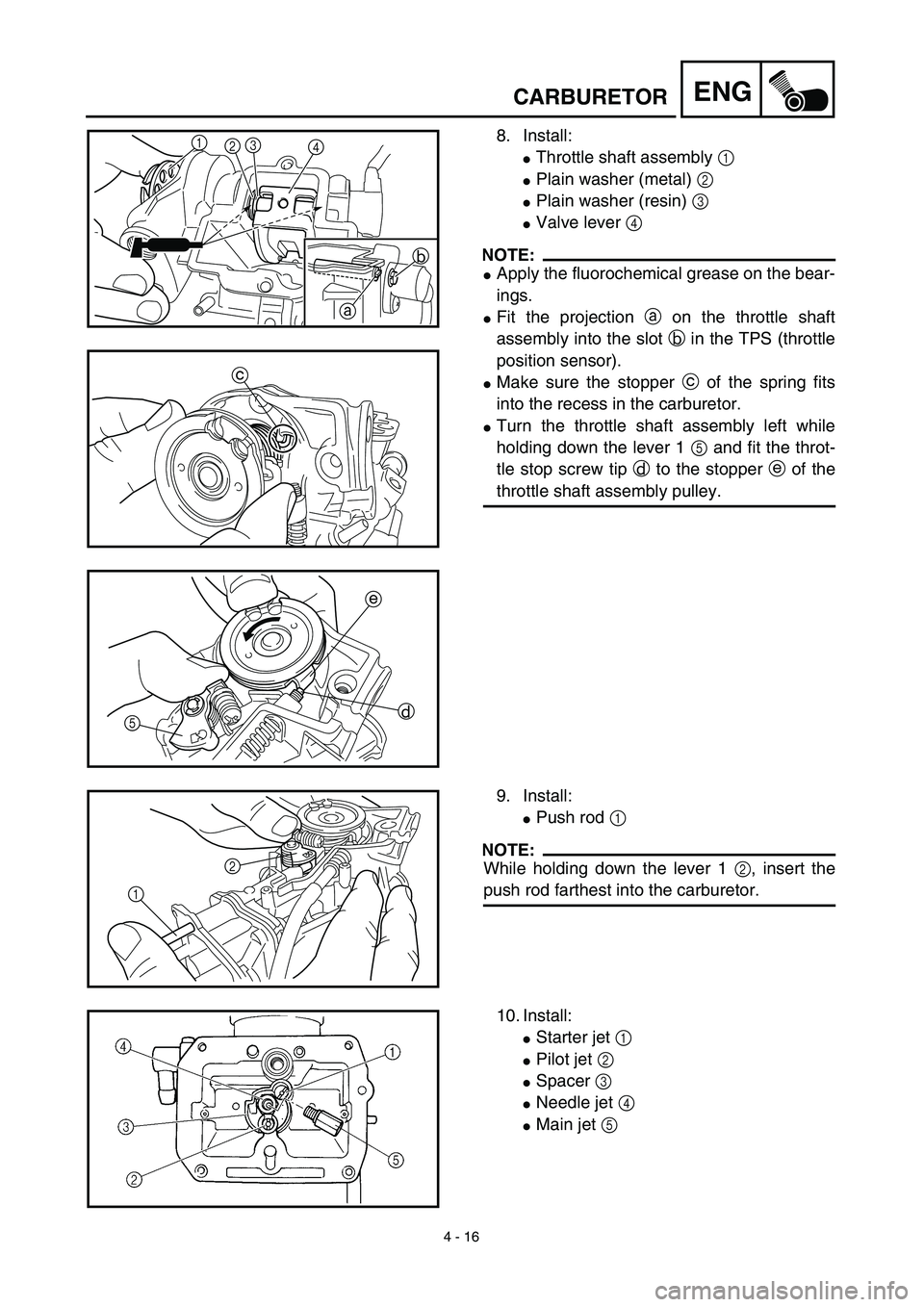
8. Install:
�Throttle shaft assembly 1
�Plain washer (metal) 2
�Plain washer (resin) 3
�Valve lever 4
NOTE:
�Apply the fluorochemical grease on the bear-
ings.
�Fit the projection a on the throttle shaft
assembly into the slot b in the TPS (throttle
position sensor).
�Make sure the stopper c of the spring fits
into the recess in the carburetor.
�Turn the throttle shaft assembly left while
holding down the lever 1 5 and fit the throt-
tle stop screw tip d to the stopper e of the
throttle shaft assembly pulley.
1
23
4
b
a
c
e
d
5
9. Install:
�Push rod 1
NOTE:
While holding down the lever 1 2, insert the
push rod farthest into the carburetor.12
10. Install:
�Starter jet 1
�Pilot jet 2
�Spacer 3
�Needle jet 4
�Main jet 5