Page 148 of 340

3 - 16
INSP
ADJ
STEERING HEAD INSPECTION AND ADJUSTMENT
3. Check:
�Steering smooth action
Turn the handlebar lock to lock.
Unsmooth action → Adjust steering ring
nut.
4. Adjust:
�Steering ring nut
Steering ring nut adjustment steps:
�Remove the front fender 1.
�Remove the handlebar and handle crown.
�Loosen the ring nut 2 using the ring nut
wrench 3.
Ring nut wrench:
YU-1268/90890-01268
�Tighten the ring nut 4 using ring nut
wrench 5 and turn the steering right and
left a few times.
NOTE:
Set the torque wrench to the ring nut wrench
so that they form a right angle.
Ring nut wrench:
YM-33975/90890-01403
T R..
Ring nut (initial tightening):
38 Nm (3.8 m • kg, 27 ft • lb)
�Loosen the ring nut one turn.
�Retighten the ring nut using the ring nut
wrench.
WARNING
Avoid over-tightening.
T R..
Ring nut (final tightening):
1 Nm (0.1 m • kg, 0.7 ft • lb)
�Check the steering shaft by turning it lock
to lock. If there is any binding, remove the
steering shaft assembly and inspect the
steering bearings.
�Install the handle crown 6, main switch
7, handlebar 8, and front fender.
2 3
5
4
8
7
6
Page 150 of 340
3 - 17
INSP
ADJ
STEERING HEAD INSPECTION AND ADJUSTMENT
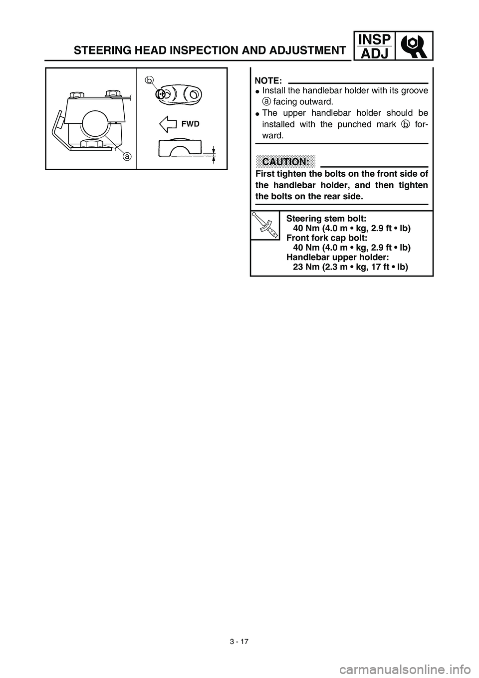
NOTE:
�Install the handlebar holder with its groove
a facing outward.
�The upper handlebar holder should be
installed with the punched mark b for-
ward.
CAUTION:
First tighten the bolts on the front side of
the handlebar holder, and then tighten
the bolts on the rear side.
T R..
Steering stem bolt:
40 Nm (4.0 m • kg, 2.9 ft • lb)
Front fork cap bolt:
40 Nm (4.0 m • kg, 2.9 ft • lb)
Handlebar upper holder:
23 Nm (2.3 m • kg, 17 ft • lb)
a
Page 286 of 340
5 - 10
CHASSTEERING
EC560000
STEERING
LS
LS
T R..TIGHTENING STEPS:
•Tighten ring nut.
38 Nm (3.8 m • kg, 27 ft • Ib)
•Loosen it completely.
•Retighten it.
1 Nm (0.1 m • kg, 0.7 ft • Ib)
T R..40 Nm (4.0 m • kg, 29 ft • Ib)
5 9681076 43
21
Extent of removal:1 Under bracket removal2 Bearing removal
Extent of removal Order Part name Q’ty Remarks
STEERING REMOVAL
WARNING
Support the machine securely so there is nodanger of it falling over.
Preparation for removal Hold the machine by placing the
suitable stand under the engine.
Front fork Refer to “FRONT FORK” section.
1 Steering stem bolt 1
2 Handle crown 1
3 Ring nut 1 Use special tool.
Refer to “STEERING HEAD INSPEC-
TION AND ADJUSTMENT” section in
the CHAPTER 3.
4 Ball race cover 1
5 Under bracket 1
6 Bearing inner race 2
7 Upper bearing ball 19
8 Lower bearing ball 16
9 Dust seal 1
10 Bearing outer race 2
2
1

•Loosen it completely.
•Retighten it.
1 Nm (0.1 m • kg, 0.7 ft • Ib")