Page 292 of 340

6 - 1
–+ELEC
12
3
456
7
0
98
A
B
F
EC
D
ELECTRICAL COMPONENTS AND WIRING DIAGRAM
EC600000
ELECTRICAL
EC610000
ELECTRICAL COMPONENTS AND WIRING DIAGRAM
EC611000
ELECTRICAL COMPONENTS
1
Main switch
2
“ENGINE STOP”
switch
3
Thermo switch
4
Ignition coil
5
CDI unit
6
Battery
7
Rectifier/regulator
8
Neutral switch
9
CDI magneto
0
Carburetor heater
A
Starter relay
B
Fuse
C
Start switch
D
Spark plug
E
Starter motor
F
Starting circuit cut-off
relay
COLOR CODE
B ...................... Black
Br .................... Brown
G ..................... Green
O ..................... Orange
R ..................... Red
Sb .................... Sky blue
W ..................... White
Y ...................... Yellow
EC612000
WIRING DIAGRAM
G/WB/RW/LW/RBr G
RW
B/WBr BRB/WBBrR
B/WB BB
BR/WBr B
GG/W
B/W
B/W
BrB/RWWOO
B
BW/LY/RR
W
B
B
R
W/RY/R
OFF RUNB
Y/R
Y
Y
OBO BY/RYB B
Sb
W W
Sb
ON OFF
OFFON
Y
BB
Y/R
Br
Br
B
B
R
RR
R
B
R/WR/W
R/WR/W
R/W
Sb
Sb
RB
R/WB R
Y/RRB W
B/WB
R/W
R/W
R/W
Sb
9
8
1 B5
4
D
2 3
=A
E 6
C
F 7
B/R ................... Black/Red
B/W .................. Black/White
G/W.................. Green/White
R/W .................. Red/White
W/L .................. White/Blue
W/R .................. White/Red
Y/R ................... Yellow/Red
Page 294 of 340
–+ELEC
6 - 2
IGNITION SYSTEM
EC620000
IGNITION SYSTEM
INSPECTION STEPS
Use the following steps for checking the possibility of the malfunctioning engine being attributable to
ignition system failure and for checking the spark plug which will not spark.
NOTE:
�
Remove the following parts before inspection.
1) Seat
2) Fuel tank
�
Use the following special tools in this inspection.
Spark gap testClean or replace
spark plug.
Check entire ignition
system for connection.Repair or replace.
Check main switch. Replace.
Check “ENGINE STOP”
switch.Replace.
Check ignition coil. Primary coil Replace.
Secondary coil Replace.
Check CDI magneto. Pickup coil Replace.
Source coil Replace.
Replace CDI unit.
Dynamic spark tester:
YM-34487
Ignition checker:
90890-06754
Pocket tester:
YU-3112-C/90890-03112
No Spark
OK
OK
OK
OK
Spark
No good
No good
No good
No good
No good
No good
OK
No good
Page 298 of 340
6 - 3
–+ELEC
IGNITION SYSTEM
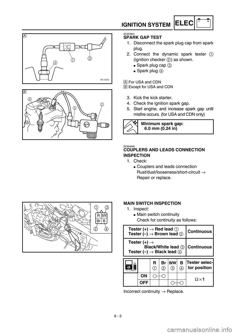
EC622001
SPARK GAP TEST
1. Disconnect the spark plug cap from spark
plug.
2. Connect the dynamic spark tester
1
(ignition checker
2
) as shown.
�
Spark plug cap
3
�
Spark plug
4
Å
For USA and CDN
ı
Except for USA and CDN
3. Kick the kick starter.
4. Check the ignition spark gap.
5. Start engine, and increase spark gap until
misfire occurs. (for USA and CDN only)
Minimum spark gap:
6.0 mm (0.24 in)
Å
ı
EC624000
COUPLERS AND LEADS CONNECTION
INSPECTION
1. Check:
�
Couplers and leads connection
Rust/dust/looseness/short-circuit
→
Repair or replace.
MAIN SWITCH INSPECTION
1. Inspect:
�
Main switch continuity
Check for continuity as follows:
Incorrect continuity
→
Replace.
Tester (+)
→
Red lead
1
Tester (–)
→
Brown lead
2
Continuous
Tester (+)
→
Black/White lead
3
Tester (–)
→
Black lead
4
Continuous
R
1
Br
2
B/W
3B
4Tester selec-
tor position
ON
Ω × 1
OFF
B/W
BrR
B
1
3
2
4
Page 300 of 340
6 - 4
–+ELECIGNITION SYSTEM
“ENGINE STOP” SWITCH INSPECTION
1. Inspect:
�“ENGINE STOP” switch continuity
No continuous while being pushed → Replace.
Continuous while being free → Replace. Tester (+) lead → Black lead 1
Tester (–) lead → Black lead 2
B
1B
2Tester selec-
tor position
PUSH IN
Ω × 1
FREE
B B
1
2
EC626002
IGNITION COIL INSPECTION
1. Inspect:
�Primary coil resistance
Out of specification → Replace.
2. Inspect:
�Secondary coil resistance
Out of specification → Replace.
NOTE:
When inspecting the secondary coil resis-
tance, remove the spark plug cap.Tester (+) lead → Orange lead 1
Tester (–) lead → Black lead 2
Primary coil
resistanceTester selector
position
0.18 ~ 0.28 Ω at
20 ˚C (68 ˚F)Ω × 1
Tester (+) lead → Spark plug lead 1
Tester (–) lead → Orange lead 2
Secondary coil
resistanceTester selector
position
6.3 ~ 9.5 kΩ at
20 ˚C (68 ˚F)kΩ × 1
Page 302 of 340
6 - 5
–+ELECIGNITION SYSTEM
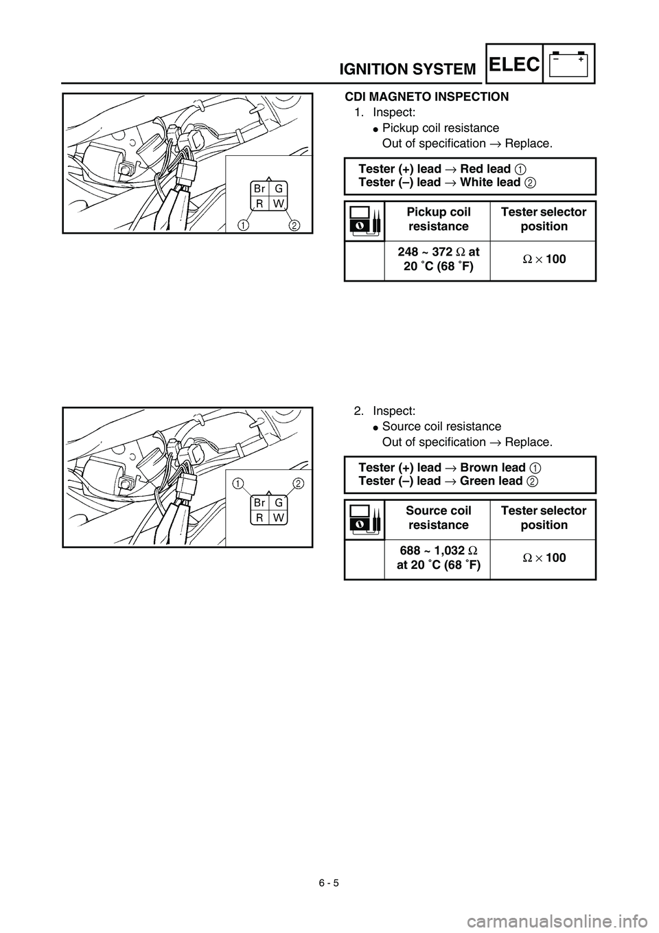
CDI MAGNETO INSPECTION
1. Inspect:
�Pickup coil resistance
Out of specification → Replace.
Tester (+) lead → Red lead 1
Tester (–) lead → White lead 2
Pickup coil
resistanceTester selector
position
248 ~ 372 Ω at
20 ˚C (68 ˚F)Ω × 100
2. Inspect:
�Source coil resistance
Out of specification → Replace.
Tester (+) lead → Brown lead 1
Tester (–) lead → Green lead 2
Source coil
resistanceTester selector
position
688 ~ 1,032 Ω
at 20 ˚C (68 ˚F)Ω × 100