Page 406 of 578
5 - 1
CHAS
FRONT WHEEL AND FRONT BRAKE (TT-R125E)
EC500000
CHASSIS
FRONT WHEEL AND FRONT BRAKE (TT-R125E)
Extent of removal:
1
Front wheel removal
2
Wheel bearing removal
3
Brake shoe plate assembly removal and disassembly
Extent of removal Order Part name Q’ty Remarks
Preparation for removal
FRONT WHEEL AND DRUM
BRAKE
Hold the machine by placing the
suitable stand under the engine.
WARNING
Support the machine securely so there is no
danger of it falling over.
1 Brake cable holder 1
2 Brake cable 1 Disconnect at the lever side, first.
3 Axle nut 1
4 Wheel axle 1
5 Front wheel 1
6 Collar set 1
7 Brake shoe plate assembly 1
8 Oil seal 1
9 Wheel bearing 2 Refer to “REMOVAL POINTS”.
10Spacer
1
2
3
1
Page 410 of 578
5 - 3
CHAS
FRONT WHEEL AND FRONT BRAKE (TT-R125E)
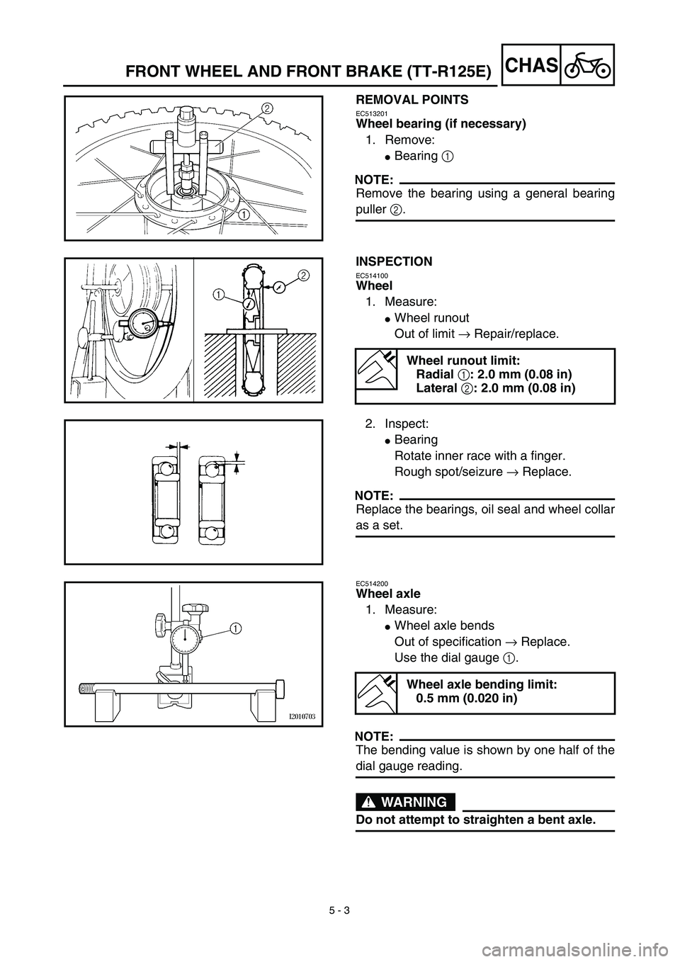
REMOVAL POINTS
EC513201
Wheel bearing (if necessary)
1. Remove:
�
Bearing
1
NOTE:
Remove the bearing using a general bearing
puller
2
.
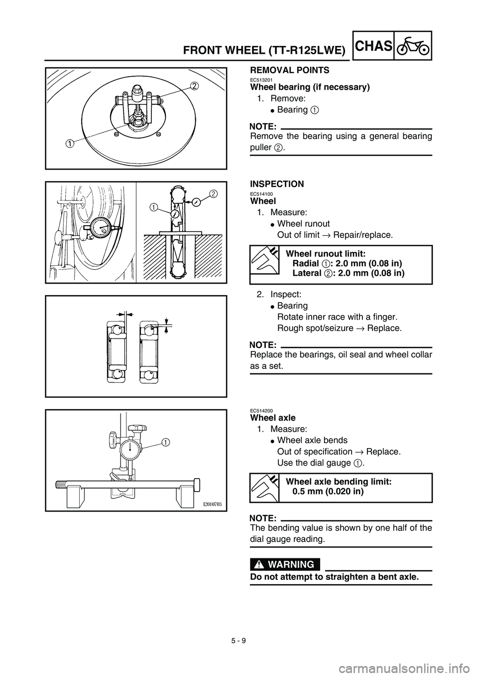
INSPECTION
EC514100
Wheel
1. Measure:
�
Wheel runout
Out of limit
→
Repair/replace.
Wheel runout limit:
Radial
1
: 2.0 mm (0.08 in)
Lateral
2
: 2.0 mm (0.08 in)
2. Inspect:
�
Bearing
Rotate inner race with a finger.
Rough spot/seizure
→
Replace.
NOTE:
Replace the bearings, oil seal and wheel collar
as a set.
EC514200
Wheel axle
1. Measure:
�
Wheel axle bends
Out of specification
→
Replace.
Use the dial gauge
1
.
NOTE:
The bending value is shown by one half of the
dial gauge reading.
WARNING
Do not attempt to straighten a bent axle.
Wheel axle bending limit:
0.5 mm (0.020 in)
Page 414 of 578
5 - 5
CHAS
FRONT WHEEL AND FRONT BRAKE (TT-R125E)
ASSEMBLY AND INSTALLATION
Brake shoe plate assembly
1. Install:
�
Brake camshaft
1
NOTE:
Apply the lithium soap base grease on the
brake camshaft.
2. Check:
�
Brake camshaft operation
Unsmooth operation
→
Repair.
3. Install:
�
Wear indicator plate
1
NOTE:
When installing the wear indicator plate to the
brake camshaft align the projection
a
on the
wear indicator plate with the slots
b
on the
brake camshaft.
4. Install:
�
Brake camshaft lever
1
NOTE:
Install the brake camshaft lever in relation to
the punch mark
a
as shown.
1
1a
T R..10 Nm (1.0 m · kg, 7.2 ft · lb)
5. Install:
�
Springs
1
�
Brake shoes 2
NOTE:
Apply the lithium soap base grease on the
pivot pin.
WARNING
Do not apply grease to the brake shoe lin-
ings.
New
Page 420 of 578
5 - 8
CHAS
FRONT WHEEL (TT-R125LWE)
Extent of removal:1 Front wheel removal2 Wheel bearing removal
3 Brake disc removal
Extent of removal Order Part name Q’ty Remarks
Preparation for removalFRONT WHEEL REMOVAL
Hold the machine by placing the
suitable stand under the engine.
WARNING
Support the machine securely so there is nodanger of it falling over.
1 Axle nut 1
2 Washer 1
3 Wheel axle 1
4 Front wheel 1
5 Collar 2
6 Oil seal 2
7 Wheel bearing 2 Refer to “REMOVAL POINTS”.
8 Spacer 1
9Brake disk
1
2
31
3
FRONT WHEEL (TT-R125LWE)
Page 422 of 578
5 - 9
CHASFRONT WHEEL (TT-R125LWE)
REMOVAL POINTS
EC513201
Wheel bearing (if necessary)
1. Remove:
�Bearing 1
NOTE:
Remove the bearing using a general bearing
puller 2.
INSPECTION
EC514100
Wheel
1. Measure:
�Wheel runout
Out of limit → Repair/replace.
2. Inspect:
�Bearing
Rotate inner race with a finger.
Rough spot/seizure → Replace.
NOTE:
Replace the bearings, oil seal and wheel collar
as a set.
Wheel runout limit:
Radial 1: 2.0 mm (0.08 in)
Lateral 2: 2.0 mm (0.08 in)
EC514200
Wheel axle
1. Measure:
�Wheel axle bends
Out of specification → Replace.
Use the dial gauge 1.
NOTE:
The bending value is shown by one half of the
dial gauge reading.
WARNING
Do not attempt to straighten a bent axle.
Wheel axle bending limit:
0.5 mm (0.020 in)
Page 428 of 578
5 - 12
CHAS
FRONT BRAKE (TT-R125LWE)
Extent of removal:1 Brake hose removal 2 Brake caliper removal
3 Brake master cylinder removal
Extent of removal Order Part name Q’ty Remarks
Preparation for removalFRONT BRAKE REMOVAL
Hold the machine by placing the
suitable stand under the engine.
Drain the brake fluid.
WARNING
Support the machine securely so there is nodanger of it falling over.
Refer to “REMOVAL POINTS”.
1 Brake hose holder 2
2 Union bolt 1
3 Brake hose 1
4 Joint 1
5 Brake caliper support bolt 1
6 Brake caliper 1 Refer to “REMOVAL POINTS”.
7 Brake lever 1
8 Brake master cylinder bracket 1
9Brake master cylinder
1
3
12
2
3
FRONT BRAKE (TT-R125LWE)
Page 430 of 578
5 - 13
CHASFRONT BRAKE (TT-R125LWE)
BRAKE CALIPER AND BRAKE MASTER CYLINDER DISASSEMBLY
Extent of removal:1 Brake caliper disassembly2 Brake master cylinder disassembly
Extent of removal Order Part name Q’ty Remarks
Preparation for removalBRAKE CALIPER AND BRAKE
MASTER CYLINDER DISAS-
SEMBLY
Hold the machine by placing the
suitable stand under the engine.
WARNING
Support the machine securely so there is no
danger of it falling over.
1Brake pad 2
2Brake caliper bracket 1
3Brake caliper piston 2
Refer to “REMOVAL POINTS”. 4Brake caliper dust seal 2
5Brake caliper piston seal 2
6Pin boot 1
7Sleeve boot 1
8Brake master cylinder cap 1
9Diaphragm 1
0Brake master cylinder boot 1
ACirclip 1
BWasher 1
CBrake master cylinder kit 1
2
1
Page 432 of 578

REMOVAL POINTS
Brake fluid
1. Remove:
�Brake master cylinder cap 1
NOTE:
Do not remove the diaphragm.
2. Connect the transparent hose 2 to the
bleed screw 1 and pl")
5 - 14
CHASFRONT BRAKE (TT-R125LWE)
REMOVAL POINTS
Brake fluid
1. Remove:
�Brake master cylinder cap 1
NOTE:
Do not remove the diaphragm.
2. Connect the transparent hose 2 to the
bleed screw 1 and place a suitable con-
tainer under its end.
3. Loosen the bleed screw and drain the
brake fluid while pulling in the lever.
CAUTION:
�Do not reuse the drained brake fluid.
�Brake fluid may erode painted surfaces or
plastic parts. Always clean up spilled
fluid immediately.
Brake caliper
1. Remove:
�Brake caliper 1
NOTE:
Turn the brake caliper counterclockwise and
pull out it from the guide pin 2 on the brake
caliper bracket.
Brake caliper piston
1. Remove:
�Brake caliper piston
Use compressed air and proceed care-
fully.
WARNING
�Cover piston with rag and use extreme
caution when expelling piston from cylin-
der.
�Never attempt to pry out piston.
Brake caliper piston removal steps:
�Insert a piece of rag into the brake caliper
to lock one brake caliper.
�Carefully force the piston out of the brake
caliper cylinder with compressed air.

EC500000
CHASSIS
FRONT WHEEL AND FRONT BRAKE (TT-R125E)
Extent of removal:
1
Front wheel removal
2
Wheel bearing removal
3
Brak")


Extent of removal:1 Front wheel removal2 Wheel bearing removal
3 Brake disc removal
Extent of removal Order Part name Q’ty Remarks
Preparation for removalFRONT WH")

Extent of removal:1 Brake hose removal 2 Brake caliper removal
3 Brake master cylinder removal
Extent of removal Order Part name Q’ty Remarks
Preparation for re")

BRAKE CALIPER AND BRAKE MASTER CYLINDER DISASSEMBLY
Extent of removal:1 Brake caliper disassembly2 Brake master cylinder disassembly
Extent of removal Order Part na")