Page 170 of 510
 3 - 10
INSP
ADJOIL PRESSURE INSPECTION/PILOT AIR SCREW
ADJUSTMENT/ENGINE IDLING SPEED ADJUSTMENT
OIL PRESSURE INSPECTION
1. Check:
�Oil pressure
Checking steps:
�Slightly loosen the oil pressure check")
3 - 10
INSP
ADJOIL PRESSURE INSPECTION/PILOT AIR SCREW
ADJUSTMENT/ENGINE IDLING SPEED ADJUSTMENT
OIL PRESSURE INSPECTION
1. Check:
�Oil pressure
Checking steps:
�Slightly loosen the oil pressure check bolt
1.
�Start the engine and keep it idling until oil
starts to seep from the oil pressure check
bolt. If no oil comes out after one minute,
turn the engine off so it will not seize.
�Check oil passages and oil pump for dam-
age or leakage.
�Start the engine after solving the prob-
lem(s) and recheck the oil pressure.
�Tighten the oil pressure check bolt.
T R..
Oil pressure check bolt:
7 Nm (0.7 m • kg, 5.1 ft • lb)
PILOT AIR SCREW ADJUSTMENT
1. Adjust:
�Pilot air screw 1
Adjustment steps:
NOTE:
To optimize the fuel flow at a smaller throttle
opening, each machine’s pilot air screw has
been individually set at the factory. Before
adjusting the pilot air screw, turn it in fully
and count the number of turns. Record this
number as the factory-set number of turns
out.
�Screw in the pilot air screw until it is lightly
seated.
�Back out by the specified number of turns.
Pilot air screw:
2-1/2 ~ 3-1/2 turns out (example)
ENGINE IDLING SPEED ADJUSTMENT
1. Start the engine and thoroughly warm it
up.
2. Attach:
�Inductive tachometer
To spark plug lead.
3. Adjust:
�Engine idling speed
Page 172 of 510
3 - 11
INSP
ADJ
VALVE CLEARANCE INSPECTION AND ADJUSTMENT
VALVE CLEARANCE INSPECTION AND
ADJUSTMENT
NOTE:
�The valve clearance should be adjusted
when the engine is cool to the touch.
�The piston must be at Top Dead Center
(T.D.C.) on compression stroke to check or
adjust the valve clearance.
1. Remove:
�Seat
�Fuel tank
Refer to “SEAT, FUEL TANK AND SIDE
COVERS” section in the CHAPTER 4. Adjustment steps:
�Adjust the pilot air screw.
Refer to “PILOT AIR SCREW ADJUST-
MENT” section.
�Turn the throttle stop screw 1 until the
specified engine idling speed.
To increase idling speed →
Turn the throttle stop screw 1 in a.
To decrease idling speed →
Turn the throttle stop screw 1 out b.
Inductive tachometer:
YU-8036-B/90890-03113
Engine idling speed:
1,300 ~ 1,500 r/min
2. Remove:
�Spark plug
�Intake tappet cover 1
�Exhaust tappet cover 2
�O-ring
3. Remove:
�Timing mark accessing screw 1
�Crankshaft end accessing screw 2
�O-ring
Page 176 of 510
3 - 13
INSP
ADJ
VALVE CLEARANCE INSPECTION AND ADJUSTMENT
�Measure the valve clearance.
�If the clearance is incorrect, repeat above
steps until specified clearance is obtained.
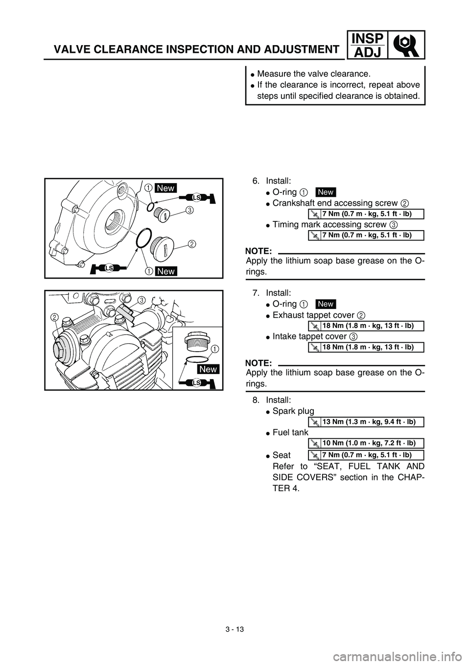
6. Install:
�O-ring 1
�Crankshaft end accessing screw 2
�Timing mark accessing screw 3
NOTE:
Apply the lithium soap base grease on the O-
rings.
New
T R..7 Nm (0.7 m · kg, 5.1 ft · lb)
T R..7 Nm (0.7 m · kg, 5.1 ft · lb)
7. Install:
�O-ring 1
�Exhaust tappet cover 2
�Intake tappet cover 3
NOTE:
Apply the lithium soap base grease on the O-
rings.
8. Install:
�Spark plug
�Fuel tank
�Seat
Refer to “SEAT, FUEL TANK AND
SIDE COVERS” section in the CHAP-
TER 4.
New
T R..18 Nm (1.8 m · kg, 13 ft · lb)
T R..18 Nm (1.8 m · kg, 13 ft · lb)
T R..13 Nm (1.3 m · kg, 9.4 ft · lb)
T R..10 Nm (1.0 m · kg, 7.2 ft · lb)
T R..7 Nm (0.7 m · kg, 5.1 ft · lb)
Page 204 of 510
 3 - 27
INSP
ADJ
STEERING HEAD INSPECTION AND ADJUSTMENT
T R..
Ring nut (final tightening):
20 Nm (2.0 m • kg, 14 ft • lb)
�Check the steering stem by turning it lock
to lock. If there is any bindi")
3 - 27
INSP
ADJ
STEERING HEAD INSPECTION AND ADJUSTMENT
T R..
Ring nut (final tightening):
20 Nm (2.0 m • kg, 14 ft • lb)
�Check the steering stem by turning it lock
to lock. If there is any binding, remove the
steering stem assembly and inspect the
steering bearings.
�Install the rubber washer 8, upper ring
nut 9 and special washer 0.
NOTE:
�Tighten the upper ring nut until it contacts
the rubber washer.
�Insert the special washer pawls into the
slots. If the slots are not aligned, tighten
the upper ring nut for alignment.
�Install the upper bracket A, steering stem
nut B, cap C, handlebar D, upper han-
dlebar holder E, starter knob nut F and
number plate G.
NOTE:
�The upper handlebar holder should be
installed with the punched mark a for-
ward.
�Insert the end of fuel breather hose H into
the hole of the starter knob stay.
CAUTION:
First tighten the bolts on the front side of
the handlebar holder, and then tighten
the bolts on the rear side.
T R..
Pinch bolt (upper bracket):
25 Nm (2.5 m • kg, 18 ft • lb)
Steering stem nut:
110 Nm (11.0 m • kg, 80 ft • lb)
Handlebar upper holder:
23 Nm (2.3 m • kg, 17 ft • lb)
Starter knob nut:
1 Nm (0.1 m • kg, 0.7 ft • lb)
Number plate:
7 Nm (0.7 m • kg, 5.1 ft • lb)
Page 210 of 510
4 - 1
ENG
EC400000
ENGINE
EC4R0000
SEAT, FUEL TANK AND SIDE COVERS
Extent of removal:
1
Seat removal
2
Fuel tank removal
3
Side covers removal
4
Number plate removal
Extent of removal Order Part name Q’ty Remarks
Preparation for removal
SEAT, FUEL TANK AND SIDE
COVERS REMOVAL
Turn the fuel cock to “OFF”.
1 Seat 1
2 Air scoop (left and right) 2
3 Fuel hose 1 Remove on fuel tank side.
4 Fitting band 1
5 Bolt (fuel tank) 2
6 Fuel tank 1
7 Left side cover 1
8 Right side cover 1
9Number plate
1
13
4
2
3
SEAT, FUEL TANK AND SIDE COVERS
Page 212 of 510
4 - 2
ENG
MUFFLER
MUFFLER
Extent of removal:
1
Muffler removal
Extent of removal Order Part name Q’ty Remarks
MUFFLER REMOVAL
Preparation for removal Right side cover Refer to “SEAT, FUEL TANK AND SIDE
COVERS” section.
1 Bolt (spark arrester) 3
2 Spark arrester 1
3 Nut (muffler) 2
4 Bolt (muffler) 1
5Muffler
1
1
Page 214 of 510
4 - 3
ENG
CARBURETOR
CARBURETOR
Extent of removal:
1
Carburetor removal
Extent of removal Order Part name Q’ty Remarks
CARBURETOR REMOVAL
Preparation for removal Fuel tank Refer to “SEAT, FUEL TANK AND SIDE
COVERS” section.
1 Fuel hose 1
2 Over flow hose 1
3 Air vent hose 2
4 Starter plunger 1
5 Carburetor top cover 1
6 Clamp (air cleaner joint) 1 Loosen the screw (air cleaner joint).
7 Clamp (carburetor joint) 1 Loosen the screws (carburetor joint).
8Carburetor
1
1
Page 218 of 510
4 - 5
ENG
CARBURETOR
HANDLING NOTE
At high altitudes, the atmospheric pressure is
lower. This can make the fuel mixture too rich,
leading to such problems as fouled.
Spark plugs and slow response at high engine
speeds. A special part, High Altitude Main Jet
1
#102.5 (620-1423A-71-A0) is available to
correct this.
EC463000
REMOVAL POINTS
Throttle valve
1. Remove:
�
Throttle valve
1
�
Spring (throttle valve)
2
�
Carburetor top cover
3
�
Throttle cable
4
NOTE:
While compressing the spring (throttle valve),
disconnect the throttle cable.
Pilot air screw
1. Remove:
�
Pilot air screw
1
NOTE:
To optimize the fuel flow at a smaller throttle
opening, each machine’s pilot air screw has
been individually set at the factory. Before
removing the pilot air screw, turn it in fully and
count the number of turns. Record this number
as the factory-set number of turns out.


4 - 1
ENG
EC400000
ENGINE
EC4R0000
SEAT, FUEL TANK AND SIDE COVERS
Extent of removal:
1
Seat removal
2
Fuel tank removal
3
Side covers removal
4
Number plate removal
Extent")

4 - 2
ENG
MUFFLER
MUFFLER
Extent of removal:
1
Muffler removal
Extent of removal Order Part name Q’ty Remarks
MUFFLER REMOVAL
Preparation for removal Right side cover Refer to “SEAT,")

4 - 3
ENG
CARBURETOR
CARBURETOR
Extent of removal:
1
Carburetor removal
Extent of removal Order Part name Q’ty Remarks
CARBURETOR REMOVAL
Preparation for removal Fuel tank Refer to “S")

4 - 5
ENG
CARBURETOR
HANDLING NOTE
At high altitudes, the atmospheric pressure is
lower. This can make the fuel mixture too rich,
leading to such problems as fouled.
Spark plugs and slow respons")