Page 496 of 510
6 - 1
–+ELEC
* The illustration shows the TT-R125LW
ELECTRICAL COMPONENTS AND WIRING DIAGRAM
EC600000
ELECTRICAL
EC610000
ELECTRICAL COMPONENTS AND WIRING DIAGRAM
EC611000
ELECTRICAL COMPONENTS
1CDI unit
2Engine stop switch
3Ignition coil
4CDI magneto
5Spark plugCOLOR CODE
B...................... Black
Br .................... Brown
G ..................... Green
O ..................... Orange
R ..................... Red
W..................... WhiteB/R .................. Black/Red
B/W ................. Black/White
G/L .................. Green/Blue
G/W ................. Green/White
W/L .................. White/Blue
W/R ................. White/Red
EC612000
WIRING DIAGRAM
Page 498 of 510
–+ELEC
6 - 2
IGNITION SYSTEM
EC620000
IGNITION SYSTEM
INSPECTION STEPS
Use the following steps for checking the possibility of the malfunctioning engine being attributable to
ignition system failure and for checking the spark plug which will not spark.
*marked: Only when the ignition checker is used.
NOTE:
�Remove the following parts before inspection.
1) Seat
2) Fuel tank
�Use the following special tools in this inspection.
Spark gap test*Clean or replace
spark plug.
Check entire ignition
system for connection.Repair or replace.
Check engine stop switch. Replace.
Check ignition coil. Primary coil Replace.
Secondary coil Replace.
Check CDI magneto. Pickup coil Replace.
Charging coil Replace.
Replace CDI unit.
Dynamic spark tester:
YM-34487
Ignition checker:
90890-06754Pocket tester:
YU-3112-C/90890-03112
No Spark
OK
OK
OK
OK
Spark
No good
No good
No good
No good
No good
No good
Page 502 of 510
6 - 3
–+ELECIGNITION SYSTEM
SPARK GAP TEST
1. Disconnect the spark plug cap from spark
plug.
2. Connect the dynamic spark tester 1
(ignition checker 2) as shown.
�Spark plug cap 3
�Spark plug 4
ÅFor USA and CDN
ıExcept for USA and CDN
3. Kick the kickstarter crank.
4. Check the ignition spark gap.
5. Start engine, and increase spark gap
until misfire occurs. (for USA and CDN
only)
Minimum spark gap:
6.0 mm (0.24 in)
Å
ı
EC624000
COUPLERS AND LEADS CONNECTION
INSPECTION
1. Check:
�Couplers and leads connection
Rust/dust/looseness/short-circuit →
Repair or replace.
ENGINE STOP SWITCH INSPECTION
1. Inspect:
�Engine stop switch conduct.
Not continuous while being pushed →
Replace.
Continuous while being freed → Replace. Tester (+) lead → Black/White lead 1
Tester (–) lead → Black lead 2
B/W
1B
2Tester selec-
tor position
PUSH IN
Ω × 1
FREE
Page 504 of 510
6 - 4
–+ELECIGNITION SYSTEM
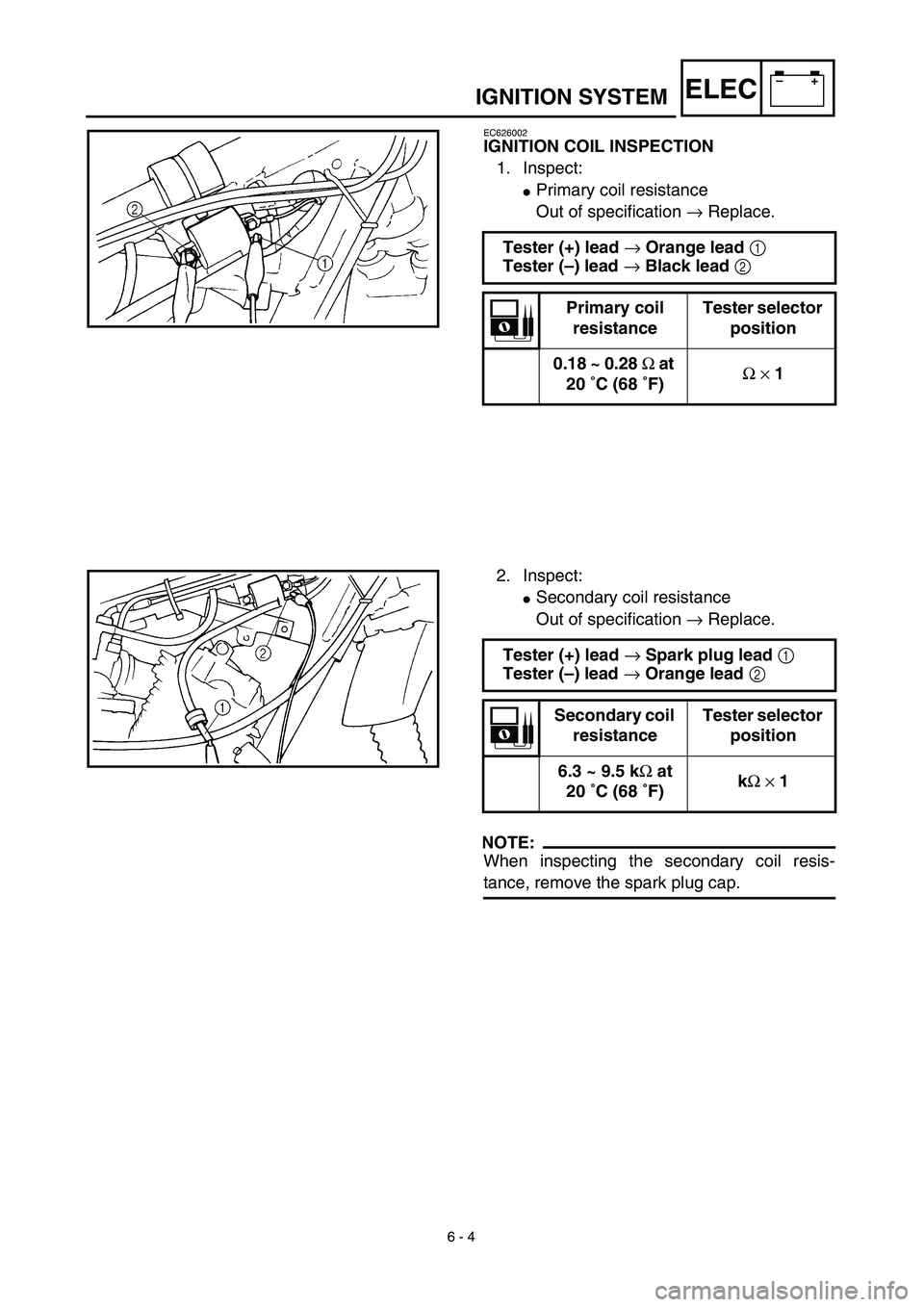
EC626002
IGNITION COIL INSPECTION
1. Inspect:
�Primary coil resistance
Out of specification → Replace.
Tester (+) lead → Orange lead 1
Tester (–) lead → Black lead 2
Primary coil
resistanceTester selector
position
0.18 ~ 0.28 Ω at
20 ˚C (68 ˚F)Ω × 1
2. Inspect:
�Secondary coil resistance
Out of specification → Replace.
NOTE:
When inspecting the secondary coil resis-
tance, remove the spark plug cap.Tester (+) lead → Spark plug lead 1
Tester (–) lead → Orange lead 2
Secondary coil
resistanceTester selector
position
6.3 ~ 9.5 kΩ at
20 ˚C (68 ˚F)kΩ × 1
Page 506 of 510
6 - 5
–+ELECIGNITION SYSTEM
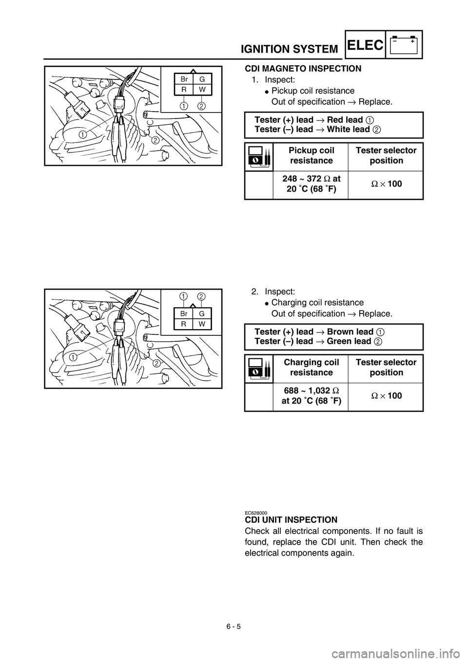
CDI MAGNETO INSPECTION
1. Inspect:
�Pickup coil resistance
Out of specification → Replace.
Tester (+) lead → Red lead 1
Tester (–) lead → White lead 2
Pickup coil
resistanceTester selector
position
248 ~ 372 Ω at
20 ˚C (68 ˚F)Ω × 100
2. Inspect:
�Charging coil resistance
Out of specification → Replace.
Tester (+) lead → Brown lead 1
Tester (–) lead → Green lead 2
Charging coil
resistanceTester selector
position
688 ~ 1,032 Ω
at 20 ˚C (68 ˚F)Ω × 100
EC628000
CDI UNIT INSPECTION
Check all electrical components. If no fault is
found, replace the CDI unit. Then check the
electrical components again.
 6 - 1
–+ELEC
* The illustration shows the TT-R125LW
ELECTRICAL COMPONENTS AND WIRING DIAGRAM
EC600000
ELECTRICAL
EC610000
ELECTRICAL COMPONENTS AND WIRING DIAGRAM
EC611000
ELECTRICAL COMPONENTS
1CDI")
 –+ELEC
6 - 2
IGNITION SYSTEM
EC620000
IGNITION SYSTEM
INSPECTION STEPS
Use the following steps for checking the possibility of the malfunctioning engine being attributable to
ignition system failure")