Page 304 of 510
4 - 48
ENGCLUTCH AND PRIMARY DRIVEN GEAR
9. Adjust:
�Push lever position
Adjustment steps:
�Loosen the locknut 1.
�Turn the push rod 1 2 clockwise or coun-
terclockwise to match alignment marks.
�Hold the push rod 1 to prevent it from
moving and tighten the locknut to specifi-
cation.
�Tighten the locknut 1.
T R..
Locknut:
8 Nm (0.8 m • kg, 5.8 ft • lb)
10. Install:
�Dowel pins
�Gasket (right crankcase cover)
�Right crankcase cover
�Bolts (right crankcase cover)
NOTE:
�Apply Quick gasket® (YAMAHA Bond
No.1215) to end of the right crankcase cover
bolts, as shown.
�Tighten the bolts in stages, using a criss-
cross pattern.
Quick gasket®:
ACC-QUICK-GS-KT
YAMAHA Bond No.1215:
90890-85505
New
T R..10 Nm (1.0 m · kg, 7.2 ft · lb)
11. Install:
�Kickstarter crank 1
�Nut (kickstarter crank) 2
NOTE:
Install the kickstarter crank so that there is 5 ~
10 mm (0.2 ~ 0.4 in) a between the kickstarter
crank and the right crankcase cover.
T R..50 Nm (5.0 m · kg, 36 ft · lb)
Page 320 of 510
4 - 56
ENGKICK AXLE AND SHIFT SHAFT
Shift shaft
1. Install:
�Shift shaft 1
NOTE:
�Apply the lithium soap base grease on the oil
seal lip of the left crankcase side.
�Hook the spring ends onto the stopper 2.
Kick axle assembly
1. Install:
�Kickstarter segment gear 1
�Plain washer 2
�Torsion spring 3
On kick axle 4.
NOTE:
Make sure the stopper a of the torsion spring
fits into the hole b on the kick axle.
2. Install:
�Spring guide 1
NOTE:
Slide the spring guide into the kick axle, make
sure the groove a in the spring guide fits on
the stopper of the torsion spring.
3. Install:
�Kick axle assembly 1
NOTE:
�Apply the engine oil on the kick axle.
�Slide the kick axle assembly into the crank-
case, make sure the clip 2 and kick axle
stopper b fit into their home positions a, c.
4. Hook:
�Torsion spring 1
NOTE:
Turn the torsion spring clockwise and hook
into the proper hole a in the crankcase.
Page 392 of 510
 5 - 14
CHASFRONT BRAKE (TT-R125LW)
REMOVAL POINTS
Brake fluid
1. Remove:
�Brake master cylinder cap 1
NOTE:
Do not remove the diaphragm.
2. Connect the transparent hose 2 to the
bleed screw 1 and pla")
5 - 14
CHASFRONT BRAKE (TT-R125LW)
REMOVAL POINTS
Brake fluid
1. Remove:
�Brake master cylinder cap 1
NOTE:
Do not remove the diaphragm.
2. Connect the transparent hose 2 to the
bleed screw 1 and place a suitable con-
tainer under its end.
3. Loosen the bleed screw and drain the
brake fluid while pulling in the lever.
CAUTION:
�Do not reuse the drained brake fluid.
�Brake fluid may erode painted surfaces or
plastic parts. Always clean up spilled
fluid immediately.
Brake caliper
1. Remove:
�Brake caliper 1
NOTE:
Turn the brake caliper counterclockwise and
pull out it from the guide pin 2 on the brake
caliper bracket.
Brake caliper piston
1. Remove:
�Brake caliper piston
Use compressed air and proceed care-
fully.
WARNING
�Cover piston with rag and use extreme
caution when expelling piston from cylin-
der.
�Never attempt to pry out piston.
Brake caliper piston removal steps:
�Insert a piece of rag into the brake caliper
to lock one brake caliper.
�Carefully force the piston out of the brake
caliper cylinder with compressed air.
Page 400 of 510
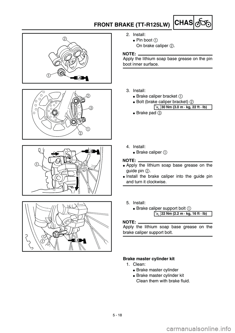
5 - 18
CHASFRONT BRAKE (TT-R125LW)
2. Install:
�Pin boot 1
On brake caliper 2.
NOTE:
Apply the lithium soap base grease on the pin
boot inner surface.
3. Install:
�Brake caliper bracket 1
�Bolt (brake caliper bracket) 2
�Brake pad 3
T R..30 Nm (3.0 m · kg, 22 ft · lb)
4. Install:
�Brake caliper 1
NOTE:
�Apply the lithium soap base grease on the
guide pin 2.
�Install the brake caliper into the guide pin
and turn it clockwise.
5. Install:
�Brake caliper support bolt 1
NOTE:
Apply the lithium soap base grease on the
brake caliper support bolt.
T R..22 Nm (2.2 m · kg, 16 ft · lb)
Brake master cylinder kit
1. Clean:
�Brake master cylinder
�Brake master cylinder kit
Clean them with brake fluid.