2003 YAMAHA TDM 900 catalytic converter
[x] Cancel search: catalytic converterPage 14 of 110

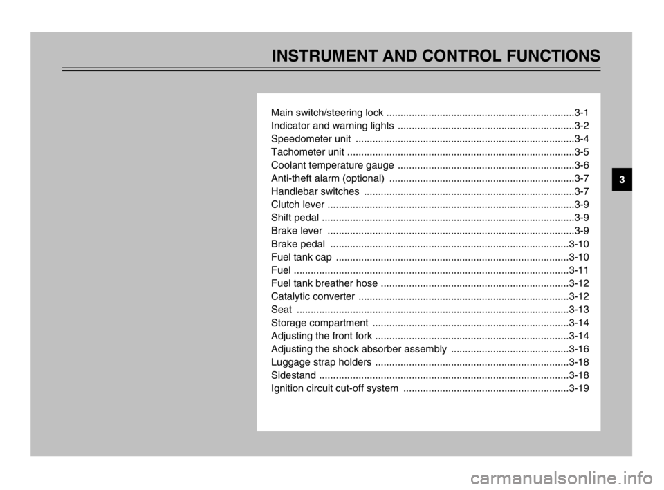
INSTRUMENT AND CONTROL FUNCTIONS
Main switch/steering lock ...................................................................3-1
Indicator and warning lights ...............................................................3-2
Speedometer unit ..............................................................................3-4
Tachometer unit .................................................................................3-5
Coolant temperature gauge ...............................................................3-6
Anti-theft alarm (optional) ..................................................................3-7
Handlebar switches ...........................................................................3-7
Clutch lever ........................................................................................3-9
Shift pedal ..........................................................................................3-9
Brake lever ........................................................................................3-9
Brake pedal .....................................................................................3-10
Fuel tank cap ...................................................................................3-10
Fuel ..................................................................................................3-11
Fuel tank breather hose ...................................................................3-12
Catalytic converter ...........................................................................3-12
Seat .................................................................................................3-13
Storage compartment ......................................................................3-14
Adjusting the front fork .....................................................................3-14
Adjusting the shock absorber assembly ..........................................3-16
Luggage strap holders .....................................................................3-18
Sidestand .........................................................................................3-18
Ignition circuit cut-off system ...........................................................3-19
3
5PS-28199-E1 8/29/02 9:16 AM Page 13
Page 26 of 110

3-12
INSTRUMENT AND CONTROL FUNCTIONS
3
ECA00104
cC
Use only unleaded gasoline. The
use of leaded gasoline will cause
severe damage to internal engine
parts, such as the valves and pis-
ton rings, as well as to the exhaust
system.
Your Yamaha engine has been
designed to use regular unleaded
gasoline with a research octane num-
ber of 91 or higher. If knocking (or
pinging) occurs, use a gasoline of a
different brand or premium unleaded
fuel. Use of unleaded fuel will extend
spark plug life and reduce mainte-
nance costs.EAU02955
Fuel tank breather hoseFuel tank breather hoseBefore operating the motorcycle:
8Check the fuel tank breather
hose connection.
8Check the fuel tank breather
hose for cracks or damage, and
replace it if damaged.
8Make sure that the end of the
fuel tank breather hose is not
blocked, and clean it if neces-
sary.
1. Fuel tank breather hose
EAU04960
Catalytic converterCatalytic converterThis motorcycle is equipped with a
catalytic converter in the muffler.
EW000128
w
The exhaust system is hot after
operation. Make sure that the
exhaust system has cooled down
before doing any maintenance
work.
5PS-28199-E1 8/29/02 9:16 AM Page 25
Page 27 of 110

3-13
INSTRUMENT AND CONTROL FUNCTIONS
3
EC000114
cC
The following precautions must be
observed to prevent a fire hazard
or other damages.
8Use only unleaded gasoline.
The use of leaded gasoline will
cause unrepairable damage to
the catalytic converter.
8Never park the motorcycle
near possible fire hazards
such as grass or other materi-
als that easily burn.
8Do not allow the engine to idle
too long.
EAU02925
Seat
SeatTo remove the seat
Insert the key into the seat lock, turn
it counterclockwise, and then pull the
seat off.
1 a
1. Seat lock
a. Unlock.
To install the seat
Insert the projections on the front of
the seat into the seat holder, push
the rear of the seat down to lock it in
place, and then remove the key.
NOTE:
Make sure that the seat is properly
secured before riding.
1. Projection (×2)
2. Seat holder (×2)
5PS-28199-E1 8/29/02 9:16 AM Page 26
Page 107 of 110

INDEX
Checking ............................................6-27
Drive chain, lubricating .........................6-28
E
Engine break-in ......................................5-3
Engine idling speed ..............................6-17
Engine oil and oil filter element ..............6-8
F
Front and rear brake pads, checking ....6-24
Front fork, adjusting ..............................3-14
Front fork, checking ..............................6-31
Fuel ......................................................3-11
Fuel consumption, tips for reducing .......5-3
Fuel tank breather hose .......................3-12
Fuel tank cap ........................................3-10
Fuses, replacing ...................................6-34
H
Handlebar switches ................................3-7
Dimmer switch .....................................3-7
Engine stop switch ...............................3-8
Hazard switch ......................................3-8
Horn switch ..........................................3-8
Pass switch ..........................................3-7
Start switch ..........................................3-8
Turn signal switch ................................3-8
Headlight bulb, replacing ......................6-35
I
Identification numbers ............................9-1
Ignition circuit cut-off system ................3-19Indicator and warning lights ....................3-2
Fuel level warning symbol ...................3-2
Turn signal indicator lights ...................3-3
High beam indicator light .....................3-3
Neutral indicator light ...........................3-3
Engine trouble warning light ................3-3
Oil level warning light ...........................3-3
K
Key identification number .......................9-1
L
Luggage strap holders ..........................3-18
M
Main switch/steering lock .......................3-1
Model label .............................................9-2
P
Parking ...................................................5-4
Part locations ..........................................2-1
Periodic maintenance and lubrication
chart .....................................................6-2
Pre-operation check list ..........................4-1
R
Rear brake light switch, adjusting .........6-24
Rear suspension, lubricating ................6-31
S
Seat ......................................................3-13
Shift pedal ..............................................3-9A
Air filter element, replacing ...................6-16
Anti-theft alarm (optional) .......................3-7
B
Battery ..................................................6-33
Brake and clutch levers, checking
and lubricating ...................................6-30
Brake and shift pedals, checking
and lubricating ...................................6-30
Brake fluid level, checking ....................6-25
Brake fluid, changing ............................6-26
Brake lever .............................................3-9
Brake pedal ..........................................3-10
Brake pedal position, adjusting ............6-23
C
Cables, checking and lubricating ..........6-29
Care ........................................................7-1
Catalytic converter ................................3-12
Clutch lever ............................................3-9
Clutch lever free play, adjusting ...........6-22
Conversion table ....................................8-5
Coolant .................................................6-11
Checking ............................................6-11
Changing ...........................................6-13
Coolant temperature gauge ....................3-6
Cowlings and panels, removing
and installing ........................................6-5
D
Drive chain slack ..................................6-27
Adjusting ............................................6-27
5PS-28199-E1 8/29/02 9:17 AM Page 106