Page 38 of 116

3-21
EAU04552
Adjusting the shock
absorber assemblies
Shock absorber assemblies, adjustingEach shock absorber assembly is
equipped with a spring preload
adjusting ring.
EC000015
cC
Never attempt to turn an adjusting
mechanism beyond the maximum
or minimum settings.
EW000040
w
Always adjust both shock
absorber assemblies equally, oth-
erwise poor handling and loss of
stability may result.
INSTRUMENT AND CONTROL FUNCTIONS
3
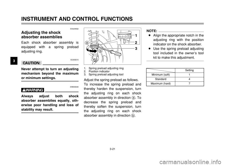
Adjust the spring preload as follows.
To increase the spring preload and
thereby harden the suspension, turn
the adjusting ring on each shock
absorber assembly in direction a. To
decrease the spring preload and
thereby soften the suspension, turn
the adjusting ring on each shock
absorber assembly in direction b.
a
b1
2
3
1. Spring preload adjusting ring
2. Position indicator
3. Spring preload adjusting tool
NOTE:
8Align the appropriate notch in the
adjusting ring with the position
indicator on the shock absorber.
8Use the spring preload adjusting
tool included in the owner’s tool
kit to make this adjustment.
Setting
Minimum (soft) 1
Standard 4
Maximum (hard) 7
5SJ-28199-E1 7/11/02 11:03 AM Page 36
Page 76 of 116

6-25
PERIODIC MAINTENANCE AND MINOR REPAIR
6
EW000077
w
Because loading has an enormous
impact on the handling, braking,
performance and safety character-
istics of your scooter, you should
keep the following precautions in
mind.
8 8
NEVER OVERLOAD THE
SCOOTER! Operation of an
overloaded scooter may result
in tire damage, loss of control,
or severe injury. Make sure
that the total weight of rider,
cargo, and accessories does
not exceed the specified maxi-
mum load for the vehicle.
8 8
Do not carry along loosely
packed items, which can shift
during a ride.
8 8
Securely pack the heaviest
items close to the center of the
scooter and distribute the
weight evenly on both sides.Tire inspection
The tires must be checked before
each ride. If the center tread depth
reaches the specified limit, if the tire
has a nail or glass fragments in it, or
if the sidewall is cracked, have a
Yamaha dealer replace the tire imme-
diately.
1a
1. Sidewall
a. Tire tread depth
8 8
Adjust the suspension and tire
air pressure with regard to the
load.
8 8
Check the tire condition and
air pressure before each ride.
Minimum tire tread depth
(front and rear)1.6 mm
5SJ-28199-E1 7/11/02 11:03 AM Page 74
Page 106 of 116
8-3
SPECIFICATIONS
8
90 kg load–maximum load*
Front200 kPa (2.00 kgf/cm
2, 2.00 bar)
Rear225 kPa (2.25 kgf/cm
2, 2.25 bar)
* Total weight of rider, passenger, cargo and accessories
Wheels
Front
Type Cast wheel
Size 12 ×MT2.75
Rear
Type Cast wheel
Size 12 ×MT3.50
Brakes
Front
Type Single disc brake
Operation Right hand
Fluid DOT 4
Rear
Type Single disc brake
Operation Left hand
Fluid DOT 4Suspension
Front Telescopic fork
Rear Unit swing
Spring/shock absorbers
Front Coil spring/oil damper
Rear Coil spring/oil damper
Wheel travel
Front 100 mm
Rear 90 mm
Electrical
Ignition system Transistorized coil ignition
(digital)
Charging system
Type A.C. magneto
Standard output 14 V, 19.5 A @ 5,000 r/min
Battery
Type GT7B-4
Voltage, capacity 12 V, 6.5 AH
Headlight bulb typeHalogen bulb
5SJ-28199-E1 7/11/02 11:03 AM Page 104