2003 VOLVO XC70 torque
[x] Cancel search: torquePage 36 of 257

2003 VOLVO XC70
accelerating. This is done by temporarily reducing engine torque to the \
drive wheels, which helps
improve tractive force.
Under certain circumstances, such as when driving with snow chains, or d\
riving in deep snow or loose
sand, it may be advisable to temporarily switch off this function for ma\
ximum tractive force. This is
done by pressing the STC/DSTC button on the center control panel for at \
least a half a second.
When the SC function has been switched off:
l The text window will briefly display "SPIN CONTROL OFF"
l The LED in the STC/DSTC button will be off.
The following two functions are only available with DSTC:
3. Active Yaw Control (AYC)
This function helps maintain directional stability, for example when cor\
nering, by braking one or more
of the wheels if the car shows a tendency to skid or slide laterally. Th\
is is done by activating the Anti-
lock Braking System. A pulsating sound will be audible when the function\
is active, which is quite
normal. If you apply the brakes while this function is active, the brake\
pedal will feel stiffer than usual.
This is also one of the DSTC system's permanent functions and is not aff\
ected when the DSTC button on
the center control panel is pressed.
4. Emergency Brake Assistance (EBA)
The EBA function is an integrated part of the DSTC system. EBA is design\
ed to provide full brake
effect immediately in the event of sudden, hard braking. The system is a\
ctivated by the speed with which
you depress the brake pedal.
When the EBA system is activated, the brake pedal will go down and press\
ure in the brake system
immediately increases to the maximum level. Maintain full pressure on th\
e brake pedal in order to utilize
the system completely. EBA is automatically deactivated when the brake p\
edal is released.
When the car has been parked for some time, the brake pedal may sink mor\
e than usual when the engine
is started. This is normal and the pedal will return to its usual positi\
on when it is released.
* Standard on all models except the T5 turbo.
** Standard on the T5 turbo, option on all other models.
pg. 21 STC/DSTC
The STC/DSTC button
file:///K|/ownersdocs/2003/2003_XC70/03xc70_01b.htm (13 of 14)12/30/20\
06 4:17:52 PM
Page 144 of 257

2003 VOLVO XC70
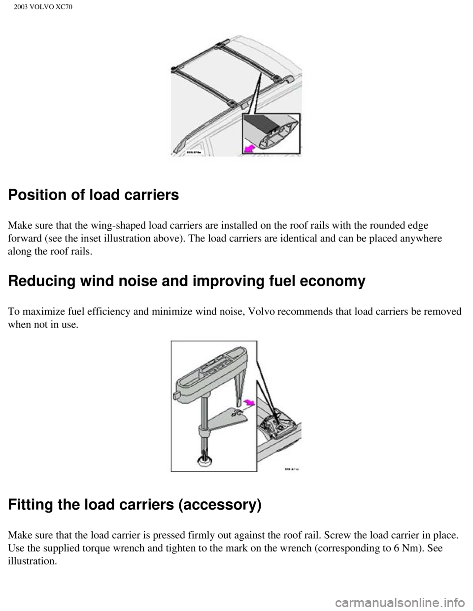
Position of load carriers
Make sure that the wing-shaped load carriers are installed on the roof r\
ails with the rounded edge
forward (see the inset illustration above). The load carriers are iden\
tical and can be placed anywhere
along the roof rails.
Reducing wind noise and improving fuel economy
To maximize fuel efficiency and minimize wind noise, Volvo recommends th\
at load carriers be removed
when not in use.
Fitting the load carriers (accessory)
Make sure that the load carrier is pressed firmly out against the roof r\
ail. Screw the load carrier in place.
Use the supplied torque wrench and tighten to the mark on the wrench (c\
orresponding to 6 Nm). See
illustration.
file:///K|/ownersdocs/2003/2003_XC70/03xc70_06a.htm (21 of 22)12/30/20\
06 4:18:00 PM
Page 145 of 257

2003 VOLVO XC70
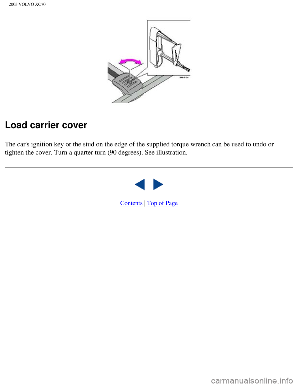
Load carrier cover
The car's ignition key or the stud on the edge of the supplied torque wr\
ench can be used to undo or
tighten the cover. Turn a quarter turn (90 degrees). See illustration.\
Contents | Top of Page
file:///K|/ownersdocs/2003/2003_XC70/03xc70_06a.htm (22 of 22)12/30/20\
06 4:18:00 PM
Page 164 of 257

2003 VOLVO XC70
Attaching the jack
NOTE: To avoid excessive wear and the necessity of rebalancing, mark and reins\
tall wheels in the same
location and position as before removal. To lessen the chance of imbalan\
ce, each wheel hub is equipped
with a guide stud to ensure that a removed wheel can be reinstalled in i\
ts original position (as when
changing over to winter tires/wheels).
NOTE: Refer to
page 133 for hoisting the vehicle on a garage lift.
Jack for AWD models
CAUTION:
l The car must not be driven with wheels of different dimensions or with a\
spare tire other than the one
that came with the car. The use of different size wheels can seriously d\
amage your car's transmission.
l Correct tightening torque on wheel bolts must be observed. The wheel bol\
ts should never be greased
or lubricated. The extended, chromed wheel bolts must not be used with s\
teel rims, as they make it
impossible to fit the hub caps.
file:///K|/ownersdocs/2003/2003_XC70/03xc70_07.htm (9 of 10)12/30/2006\
4:18:01 PM
Page 207 of 257

2003 VOLVO XC70
Engine specifications
Designation: Volvo B 5234 T3
Output 247 hp at 5200 rpm (184 kW/87 rps)
Max. torque 243 ft. lbs. at 2400-5200 rpm (330 Nm/42-87
rps)
Number of
cylinders 5
Bore 3.19" (81 mm)
Stroke 3.54" (90 mm)
Displacement 2.3 liters
Compression ratio 8.5:1
Number of valves 20
Designation: Volvo B 5254 T2
Output 208 hp at 5000 rpm (154 kW/83 rps)
Max. torque 236 ft. lbs. at 1500-4500 rpm (320 Nm/25-75
rps)
Number of
cylinders 5
Bore 3.27" (83 mm)
Stroke 3.67" (93.2 mm)
Displacement 2.5 liters
Compression ratio 9.0:1
Number of valves 20
Designation: Volvo B 5244 T3
Output 197 hp at 6000 rpm (147 kW/100 rps)
Max. torque 210 ft. lbs. at 1800-5000 rpm (285 Nm/30-83
rps)
Number of
cylinders 5
Bore 3.27" (83 mm)
Stroke 3.54" (90 mm)
file:///K|/ownersdocs/2003/2003_XC70/03xc70_09.htm (5 of 11)12/30/2006\
4:18:05 PM
Page 208 of 257

2003 VOLVO XC70
Displacement 2.4 liters
Compression ratio 9.0:1
Number of valves 20
Designation: Volvo B 5244 S
Output 168 hp at 6000 rpm (125 kW/100 rps)
Max. torque 166 ft. lbs. at 4500 rpm (225 Nm/75
rps)
Number of
cylinders 5
Bore 3.27" (83 mm)
Stroke 3.54" (90 mm)
Displacement 2.4 liters
Compression ratio 10.3:1
Number of valves 20
Charge air cooler (Intercooler)
Turbocharged engines employ a turbo-compressor to force air into the eng\
ine inlet manifold and a
charge air cooler to cool the compressed inlet air. The resulting increa\
se in air flow raises pressure in the
intake manifold and increases engine power over that developed by A norm\
ally-aspirated engine. The
charge air cooler (which resembles a radiator) is located between the \
turbo-compressor and inlet
manifold.
pg. 145 Transmission specifications
Power transmission
Manual transmission: M 56 LK
Single-disc dry plate clutch. All-synchromesh on all gears including rev\
erse; integrated final drive.
Operation via a floor mounted gear lever.
Final drive ratio 4.00:1
Reduction ratios
1st gear 3.39:1
2nd gear 1.91:1
3rd gear 1.19:1
4th gear 0.87:1
5th gear 0.70:1
file:///K|/ownersdocs/2003/2003_XC70/03xc70_09.htm (6 of 11)12/30/2006\
4:18:05 PM
Page 209 of 257

2003 VOLVO XC70
Reverse 3.30:1
Automatic transmission: AW 55-50
5-speed automatic electronically controlled gearbox comprising a hydraul\
ic torque converter with a lock-
up function; planetary gear, integrated final drive.
Operation via a floor mounted gear selector lever. Drive shafts with sym\
metrical joint location.
Overdrive.
Final drive ratio 2.44:1*
Reduction ratios AW5
1st gear 4.77:1
2nd gear 2.10:1
3rd gear 1.96:1
4th gear 1.32:1
5th gear 1.02:1
Reverse 3.23:1
* XC70 2.65:1
pg. 146 Oil/fluid specifications and volumes
Engine Oil
Meeting or exceeding ILSAC specification GF-2, including ACEA A1, API SJ\
, SJ/CF, and SJ/Energy
Conserving.
Oil additives must not be used.
Volume:
Capacity (including oil filter): 6.1 US qts. (5.8 liters)
Automatic Transmission Fluid
AW5: Only Volvo gearbox oil (1161540-8). Do not mix with other oils. \
Volume: 7.9 US qts (7.5 liters)
Cooling system
Type: Positive pressure, closed system. The thermostat begins to open at 194 \
°F (90 °C)
file:///K|/ownersdocs/2003/2003_XC70/03xc70_09.htm (7 of 11)12/30/2006\
4:18:05 PM
Page 211 of 257

2003 VOLVO XC70
Distributor ignition system
Firing order: 1-2-4-5-3
Electronic ignition setting: Not adjustable
Spark plugs: Champion RC8PYP 8 (or equivalent)
Spark plug gap: 0.028-0.032" (0.7-0.8 mm)
Tightening torque: 18.4 ft. lbs. (25 Nm) WARNING!
The ignition system operates at very high voltages. Special safety preca\
utions must be followed to
prevent injury. Always turn the ignition off when:
l Replacing ignition components e.g. plugs, coil, etc.
l Do not touch any part of the ignition system while the engine is running\
. This may result in a shock
and bodily injury.
Front suspension
Spring strut suspension with integrated shock absorbers and control arms\
linked to the support frame.
Power-assisted rack and pinion steering. Safety type steering column. Th\
e alignment specifications
apply to an unladen car but include fuel, coolant and spare wheel.
Rear suspension
Individual rear wheel suspension with longitudinal support arms, double \
link arms and track rods.
All specifications are subject to change without prior notice.
pg. 148 Electrical system
Electrical system
12 Volt, negative ground.
Voltage-controlled generator. Single-wire system with chassis and engine\
used as conductors. Grounded
on chassis.
Battery
file:///K|/ownersdocs/2003/2003_XC70/03xc70_09.htm (9 of 11)12/30/2006\
4:18:05 PM