2003 SKODA FABIA ECO mode
[x] Cancel search: ECO modePage 2 of 233

Introduction
You have opted for a Škoda - our sincere thanks for your confidence in us.
Your new Škoda offers you a vehicle featuring the most mode rn engineering and a wide range of equipment
which you will undoubtedly wish to use to the full during your daily motoring. We therefore recommend that
you read this Owner's Manual attentively to enable you to become familiar with your vehicle and all that it
offers as quickly as possible.
Please do not hesitate to contact your Škoda dealer or importer should you have any further questions
regarding your vehicle or any problems which may arise. He will be ready at any time to receive your ques-
tions, suggestions and criticisms.
Any national legal pro visions which vary from the information contained in this Owner's Manual take prec-
edence over the information contained herein.
We wish you much pleasure with your Škoda and pleasant motoring at all times.
Your Škoda Auto
Page 3 of 233

Introduction
2
The on-board literature
The on-board literature for your vehicle consists of this “ Owner's
Manual” as well as a “ Service plan”, “Te c h n i c a l d a ta ” and a
“Travelling assistant ”. There can also be a variety of other addi-
tional operating manuals and instructions on-board (e.g. an oper-
ating manual for the radio) depending on the vehicle model and
equipment.
If one of the publication s listed above is missing, please contact
a Škoda dealer immediately, where one will be glad to assist you
in such matters.
One should note that the details given in the vehicle's
papers always take precedence over those in the Owner's
Manual.
The Owner's Manual
In addition to information regarding all the controls and equip-
ment, the Owner's Manual also contains important information
regarding care and operation for your safety and also to retain the
value of your vehicle To provide you with valuable tips and aids.
You can learn how how you can operate your vehicle safely,
economically and in an environmentally conscious way.
For safety reasons, please also pay attention to the informa-
tion on accessories, modifications and replacement of parts
⇒ page 194.
The other chapters of the Owner's Manual are also important,
however, for proper treatment of your car - in addition to regular
care and maintenance - helps to retain its value and in many
cases is also one of the requirements for warranty claims. The Service Schedule
contains:
•Vehicle data
•Service intervals
•Overview of the service work
•Service proof
•Confirmation of mobility warranty
•important information on the warranty
The confirmation of the service work carried out is a requirement
for a warranty claim.
Please always present the Service Schedule when you take your
car to a Škoda dealer.
If the Service Schedule is missing or worn, please contact your
Škoda dealer, where your car is serviced regularly. You will
receive a duplicate, in which the previously carried out service
work are confirmed.
Assistance in Europe
contains the addresses and telephone numbers of Škoda
Importers.
Technical Data
includes the most important identification data of your vehicle.
Page 12 of 233

Cockpit11
Using the systemSafetyDriving TipsGeneral MaintenanceBreakdown assist-
anceTechnical DataFabia Praktik
Cockpit
An overview
This general view is designed to help you to quickly
become familiar with the instruments, gauges and
controls.
Electric exterior mirror adjustment* . . . . . . . . . . . . . . . . . . .
Air outlet vents . . . . . . . . . . . . . . . . . . . . . . . . . . . . . . . . . . .
Lever for the multi-functional switch:
−Turn signal light, headlight and parking light, headlight
flasher . . . . . . . . . . . . . . . . . . . . . . . . . . . . . . . . . . . . . . .
− Speed regulating system* . . . . . . . . . . . . . . . . . . . . . . . .
Instrument cluster: Instruments and indicator lights . . . . . .
Lever for the multi-functional switch:
− Multi-functional indicator* . . . . . . . . . . . . . . . . . . . . . . . .
− Windshield wiper/wash system . . . . . . . . . . . . . . . . . . . .
Air outlet vents . . . . . . . . . . . . . . . . . . . . . . . . . . . . . . . . . . .
Control dial for heating on the driver's seat* . . . . . . . . . . . .
Switch for rear window heater . . . . . . . . . . . . . . . . . . . . . . .
Depending on equipment fitted:
− Switch for the ESP* . . . . . . . . . . . . . . . . . . . . . . . . . . . . .
− Switch for the TCS* . . . . . . . . . . . . . . . . . . . . . . . . . . . . .
Switch for hazard warning lights . . . . . . . . . . . . . . . . . . . . .
Indicator light for a switched-off airbag* . . . . . . . . . . . . . . . .
Control dial for heating on the front passenger seat* . . . . .
Front passenger airbag* . . . . . . . . . . . . . . . . . . . . . . . . . . .
Switch for:
− Central locking system* . . . . . . . . . . . . . . . . . . . . . . . . . . −
Electric power-operated window* . . . . . . . . . . . . . . . . . .
Light switch, control dial for the instrument lighting and
control dial for the headlight beam range regulatiion . . . . .
Bonnet release lever . . . . . . . . . . . . . . . . . . . . . . . . . . . . . .
Storage compartments . . . . . . . . . . . . . . . . . . . . . . . . . . . .
Lever for adjusting the steering wheel* . . . . . . . . . . . . . . .
Headlight flasher, driver airbag . . . . . . . . . . . . . . . . . . . . . .
Ignition lock . . . . . . . . . . . . . . . . . . . . . . . . . . . . . . . . . . . . .
Depending on equipment fitted:
− Operating controls for the heating . . . . . . . . . . . . . . . . .
− Operating controls for the air conditioning system* . . . .
Ashtray . . . . . . . . . . . . . . . . . . . . . . . . . . . . . . . . . . . . . . . .
Depending on equipment fitted:
− Gearshift lever (manual gearbox) . . . . . . . . . . . . . . . . . .
− Selector lever (automatic gearbox*) . . . . . . . . . . . . . . . .
Radio*
Storage compartments . . . . . . . . . . . . . . . . . . . . . . . . . . . .
Note
•Equipment which is marked * is only standard on certain vehicle model
versions or only suppliable as optional equipment for certain models.
•Vehicles with factory-fitted radio, mobile phone, navigation system, CD
player etc. are supplied with separate instructions for operating such
equipment.
•The arrangement of the controls and switches and the location of
some items on right-hand drive models may differ from that shown in
⇒ page 10, fig. 2 . The symbols on the controls and switches are the same
as for left-hand drive models.
A162
A289
A3
54
100
A412
A5
17
59
A689
A766
A858
A9
141
142
A1054
A11128
A1266
A13122
A14
42 47
A1552, 53
A16171
A1781
A1895
A19122
A2095
A21
87
90
A2279
A23
98
104
A24
A2581
Page 17 of 233

Instruments and Indicator/Warning Lights
16
Resetting Service Interval Display
We recommend having this resetting performed by a Škoda Dealer.
Škoda dealer:
•resets the memory of the display after the appropriate inspection;
•makes an entry in the Service Schedule;
•affix the sticker to the side of the dash panel on the driver's side, where
the following service interval is shown.
The service interval displays can also be reset as follows by using the
reset button for the counter for distance driven:
Models with fixed service intervals (QG0)
Switch off the ignition, press the reset button of the trip counter for
distance driven and hold it down.
Switching the ignition on causes a service interval to appear in the display.
Holding the reset button down for 10 seconds will cause the counter to be
reset (the display shows “- - -” and then the trip counter readout).
The readout OIL will appear in the display after resetting the indicator
INSP and releasing the reset button when both service intervals (INSP
and OIL) were reached together.
Repress the reset button and hold it down for 10 seconds to also reset this
interval.
Vehicles with extended service intervals (QG1 and QG2)
Switch off the ignition, press the reset button of the trip counter for
distance driven and hold it down.
Switch the ignition on and release the reset button. Now turn the reset
button to the right. All counters will be reset to 0.
Caution
We recommend that you do not reset the Service Interval Display yourself
otherwise this can result in the service interval display being incorrectly
set, which may also result in problems with operation of your vehicle.
Note
•Information is retained in the Service Interval Display also after the
battery of the vehicle is disconnected.
•It is necessary to re-code the Service Interval Display if a new instru-
ment cluster is installed during repair work. this work is carried out by a
Škoda dealer.
•Never reset the display between service intervals otherwise this may
result in incorrect readouts.
•The data displayed is the same after resetting the display with flexible
service intervals (QG1) using the reset button as that for a vehicle with
fixed service intervals (QG2).
•We therefore recommend having the Service Interval Display reset
only by a Škoda dealer who is familiar with the procedure for resetting the
display with a vehicle system tester.
•Please refer to the brochure Service Plan for extensive information
about the service intervals.
Digital clock
A reset button is installed on the left below beside the speedom-
eter for adjusting the clock ⇒page 12, fig. 3 .
Set hours
– Turn the reset button to the left.
Page 53 of 233

Lights and Visibility
52
Lights and Visibility
Lights
Switching lights on and off
Switching on side lights
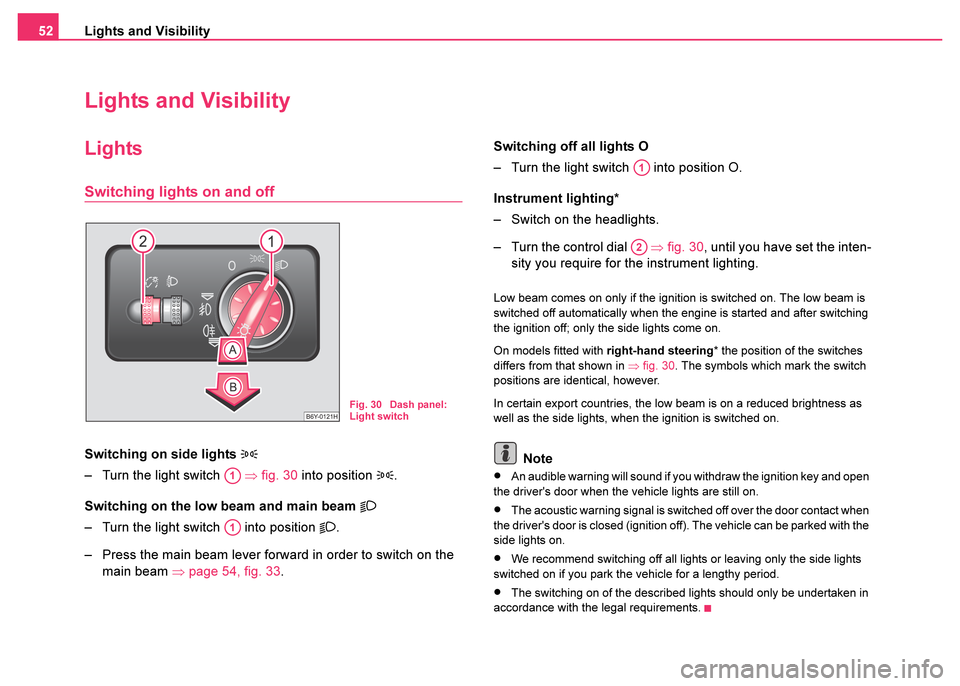
– Turn the light switch ⇒fig. 30 into position .
Switching on the low beam and main beam
– Turn the light switch into position .
– Press the main beam lever forward in order to switch on the main beam ⇒page 54, fig. 33 . Switching off all lights O
– Turn the light switch into position O.
Instrument lighting*
– Switch on the headlights.
– Turn the control dial
⇒fig. 30 , until you have set the inten-
sity you require for the instrument lighting.
Low beam comes on only if the ignition is switched on. The low beam is
switched off automatically when the engine is started and after switching
the ignition off; only the side lights come on.
On models fitted with right-hand steering* the position of the switches
differs from that shown in ⇒fig. 30. The symbols which mark the switch
positions are identical, however.
In certain export countries, the low beam is on a reduced brightness as
well as the side lights, when the ignition is switched on.
Note
•An audible warning will sound if you withdraw the ignition key and open
the driver's door when the vehicle lights are still on.
•The acoustic warning signal is switched off over the door contact when
the driver's door is closed (ignition off). The vehicle can be parked with the
side lights on.
•We recommend switching off all lights or leaving only the side lights
switched on if you park the vehicle for a lengthy period.
•The switching on of the described lights should only be undertaken in
accordance with the legal requirements.
Fig. 30 Dash panel:
Light switch
A1
A1
A1
A2
Page 84 of 233

Seats and Stowage83
Using the systemSafetyDriving TipsGeneral MaintenanceBreakdown assist-
anceTechnical DataFabia Praktik
Cooling of storage compartment on front passenger
side*
The storage compartment is for vehicles fitted with an air-
conditioning system with a closable inlet for cooled air.
– You can switch the cooling system on or off using the control
dial ⇒ fig. 71.
Opening the air inlet when the air conditioning system is on causes fresh
or interior air to flow into the storage compartment.
The cooling of the storage compartment operates only if the air condi-
tioning system is switched on. We recommend that you switch off the
cooling (opening concealed) if it is operating in the heating mode or if you
are not using the cooling system for the storage compartment.
Storage compartments on the driver's side
- storage compartment below steering wheel.
The lockable storage compartment is opened by folding down the
cover in the direction of arrow ⇒fig. 72 .
Storage compartment is for vehicles fitted with an air conditioning
system with a closable inlet for thermally prepared air.
The air supply in the storage compartment is regulated through the pull
out cap . Pulling out the end cover in the direction of travel causes the
air inlet to open while pushing it in causes the air inlet to close.
At open air supply, air flows into the storage with a temperature which is
as high as the one out of the air outlet nozzles, depending on temperature
setting.
The air inlet in the storage compartment is connected to position
through adjustment of the control dial for air distribution. This position
causes the maximum amount of air to flow into the storage compartment
(depending on the rotary regulator position for the fan).
Fig. 71 Storage
compartment: Using
cooling system
Fig. 72 Dash panel:
Storage compartments
on the driver's side
AA
AB
AB
AC
Page 89 of 233

Heating and air conditioning system
88
Note
•The whole heat output will be needed to unfrost the windscreen and
side windows. No warm air will be fed to the footwell. This can lead to
restriction of the heating comfort.
•The used air streams out through the air removal openings in the
luggage compartment.
Set heating
Recommended settings of heating controls for:
Defrosting the windscreen and side windows
•Turn control dial ⇒page 87, fig. 78 to the right up to the stop
•Control dial in the position 4
•Control dial in the position
•Open air outlet vents 4 ⇒ page 89, fig. 79 and point towards the side
window.
Keeping windscreen and side windows demisted
We recommend that you use the following setting in cases where the
windows are misted up more than usual (e.g. when it is raining):
•Control dial where necessary to the heating range
•Control dial in position 2 or 3
•Control dial to or as required or to any desired position
between these symbols
•Open air outlet vents 4 and point towards the side window
Warming up the inside of the vehicle as rapidly as possible
•Turn control dial to the right up to the stop
•Control dial in the position 4
•Control dial in the position
•Open the air outlet vents 4
•We recommend pressing button air recirculation mode. The
windows can steam up in this position however.
Heating the vehicle to a comfortable temperature
We recommend the following setting once the windows are no longer
misted up and the desired teperature has been reached:
•Control dial at the desired heat output
•Control dial in position 2 or 3
•Control dial in the position
•Open the air outlet vents 4
•Set the air distribution regulator as required between positions
and , if the windscreen gets misted up again.
Fresh air mode - ventilation
Non- pre-warmed fresh air streams through the air inlet nozzles 3 and 4
for the following settings.
Recirculated air mode must not be switched on.
•Turn the control dial ⇒ page 87, fig. 78 to the left up to the stop
•Control dial into the desired position
•Control dial in the position
•Open air outlet vents 3 and 4 ⇒page 89, fig. 79
WARNING
You should not leave recirculated air mode on over a longer period
of time. “Stale air” may result in fatigue in the driver and passen-
gers, reduce attention levels and also cause the windows to mist
up. The risk of having an accident increases. Switch recirculated
air mode off as soon as the windows begin misting up.
AA
AB
AC
AA
AB
AC
AA
AB
AC
AD
AA
AB
AC
AC
AA
AB
AC
Page 91 of 233

Heating and air conditioning system
90
The air conditioning system*
Description
The air conditioning system is a combined cooling and
heating system. It makes it possible to optimally control
the air temperature at any season of the year.
Description of the air conditioning system
It is important for your safety and for your driving comfort that the air condi-
tioning system is operating properly.
The air conditioning system operates when button ⇒page 91, fig. 80
is pressed and the following conditions are met:
•engine running,
•outside temperature above +5°C and
•blower switch switched on (positions 1 to 4).
If the air conditioning system is switched on, the temperature and air
humidity drops in the vehicle. The wellbeing of the occupants of the car is
enhanced as a result of this particularly at high outside temperatures and
a high air humidity. The system prevents the windows misting up during
the cold season of the year.
The heating effect is dependent upon the coolant temperature, thus full
heat output only occurs when the engine has reached its operating
temperature.
It is possible to briefly activate recirculated air mode in order to enhance
the cooling effect ⇒.
Air at a temperature of about 5°C may flow out of the vents under certain
circumstances when the air conditioning system is operating. Lengthy and
uneven distribution of the air flow out of the vents (in particular at the leg area) and large differences in temperature, for example when getting out
of the vehicle, can result in chills in sensitive persons.
The air inlet in front of the windscreen must be free of ice, snow or leaves
in order to ensure that the heating and ventilation systems operate prop-
erly.
Condensation from the evaporator of the air conditioning may drip down
and form a puddle below the vehicle. This is quite normal and not an indi-
cation of a leak!
Note
•We recommend that you do not smoke in the vehicle when the recir-
culating air mode is operating since the smoke which is drawn into the
evaporator from the interior of the vehicle forms deposits in the evapo-
rator of the air conditioning system. This produces a permanent odour
when the air conditioning system is operating which can only be elimi-
nated through considerable effort and expense (replacement of
compressor).
ACAE
WARNING
•For your own safety and that of other road users, ensure that all
the windows are free of ice, snow and misting. Please familiarize
yourself about how to correctly operate the heating and ventilation
systems, how to demist and defrost the windows, as well as with
the cooling mode.
•You should not leave recirculated air mode on over a longer
period of time. “Stale air” may result in fatigue in the driver and
passengers, reduce attention levels and also cause the windows to
mist up. The risk of having an accident increases. Switch recircu-
lated air mode off as soon as the windows begin misting up.