Page 150 of 183

10-02-2003
YOUR 607 IN DETAIL139
In the "OFF" position, the passenger
air bag will not be triggered in the event of an impact. As soon as the child seat is removed, turn the air bag slot to the"ON" position to re-activate the air
bag and thus ensure the safety ofyour passenger in the event of animpact. Operating check This is confirmed by an indicator light, accompanied by an audible sig-nal and a message on the multi-func-
tion display.
With the ignition on (2ndnotch), illumination of thiswarning light accompaniedby an audible signal and themessage "Passenger air
bag disarmed" on the multi-function
display, indicates that the passengerair bag is disarmed (switch in the"OFF" position). SIDE AIR BAGS AND
CURTAIN AIR BAGS The side air bags are incorporated into the frame of the front seat back,on the door side. The curtain air bags are incorporated into the door pillars and the upperpart of the passenger compartment. They are deployed independently of each other depending on which sidethe collision occurs. Operating check This is confirmed by a light on the instrument panel, accompanied byan audible signal and a message on
the multiÐfunction display.
If this indicator light comes on, accompanied by anaudible signal and the mes-sage 'Air bag(s) faulty' ,
contact a PEUGEOT dealer
to have the system checked.
Page 160 of 183
10-02-2003
PRACTICAL INFORMATION149
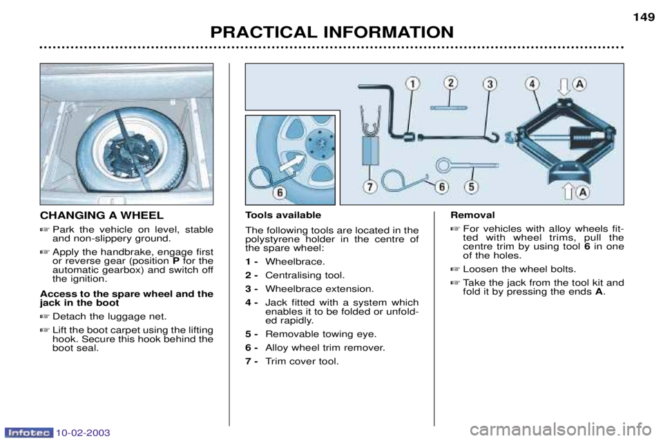
CHANGING A WHEEL
� Park the vehicle on level, stable and non-slippery ground.
� Apply the handbrake, engage firstor reverse gear (position Pfor the
automatic gearbox) and switch offthe ignition.
Access to the spare wheel and thejack in the boot � Detach the luggage net.
� Lift the boot carpet using the liftinghook. Secure this hook behind theboot seal. Tools available The following tools are located in the polystyrene holder in the centre ofthe spare wheel: 1 -
Wheelbrace.
2 - Centralising tool.
3 - Wheelbrace extension.
4 - Jack fitted with a system which enables it to be folded or unfold-
ed rapidly.
5 - Removable towing eye.
6 - Alloy wheel trim remover.
7 - Trim cover tool. Removal
� For vehicles with alloy wheels fit-ted with wheel trims, pull thecentre trim by using tool 6in one
of the holes.
� Loosen the wheel bolts.
� Take the jack from the tool kit andfold it by pressing the ends A.
Page 169 of 183
.
13* 20")
10-02-2003
Fuse N¡ RatingFunctions
10* 20 AAutomatic headlamp lighting control unit.
11* 70 A Built-in systems interface.
12* 70 A Ignition supply (+ve accessories / ignition controlled +ve).
13* 20 A Automatic headlamp lighting control unit.
14 15 A Double injection relay supply.
15* - Not used.
16* - Not used.
17* 30 A ESP hydraulic unit.
18 30 A Ignition supply (+ starter).
19 20 A Variable suspension control unit.
20 10 A Fan unit relay - Cruise control safety switch - Manual gearbox clutch switch - Manual gearbox reversing lights switch or automatic gearbox multi-function switch -
Automatic headlamp lighting control unit - Vehicle speed sensor - Coolant level sensor -
Water in diesel sensor - Power switch control unit relay.
21 5 A Automatic gearbox control unit - Automatic gearbox multi-function switch.
22 25 A ESP control unit.
23 15 A Diesel heating.
24 5 A Engine management control unit Ð Dual control control unit.
25 10 A Fuel pump.
26 30 A Driver's seat memory control unit.
27 25 A Double injection relay supply.
28 10 A Throttle housing de-icing resistor, Intake pilot solenoid valve - Flow meter - Piston de-activator injectionpump - Oil heating.
29 30 A Air pump, diesel additive control unit - Diesel additive injector.
30 - Cannot be used.
31 5 A Automatic gearbox shift lock.
32 10 A ESP or ABS control unit.
33 15 A Automatic gearbox control unit - Automatic gearbox multi-function switch (except reversing lights) - Automaticgearbox sequential control.
34 5 A Oxygen sensors - Exhaust gas recirculation solenoid valve, Exhaust gas recirculation throttle solenoid valve -
Turbo pressure regulation solenoid valve.
PRACTICAL INFORMATION
158
Page 172 of 183

10-02-2003
PRACTICAL INFORMATION159
CHANGING A WINDSCREEN WIPER BLADE Placing the wiper blades in the maintenance position � Less than one minute after switch-
ing off the ignition, activate thewindscreen wiper stalk to positionthe blades in the centre of thewindscreen (maintenance posi-tion).
Replacing a blade � Lift the arm, then unclip the bladeand remove it.
� Fit the new blade and fold downthe arm.
To park the blades, switch on theignition and operate the wind-screen wiper stalk.
REMOVING A MAT When removing a mat on the driver's or passenger's side, push back theseat as far as possible and removethe clips.
To remove a rear mat, push the cor- responding front seat forward andremove the clip. On refitting, position the mat and press firmly to refit the securing clips.
LOAD REDUCTION FUNC- TION When driving, certain functions (air conditioning, heated rear screen,heating system for passenger com-partment of diesel vehicles, etc.)
may be switched off temporarily,depending on the level of batterycharge. Reactivation of these functions is automatic, once the battery charge is
sufficient. Note:
at the risk of discharging the
battery, the functions that have been
switched off may be reactivated
manually.
A flat battery prevents the engine from starting.
ECONOMY MODE FUNCTION After the engine has stopped, certain
functions (windscreen wiper, electricwindows, sunroof, rear electric blind,electric seats, audio equipment, tele-phone etc) can only be used for thir-ty minutes, to prevent discharging
the battery.
Once the thirty minutes are over, the message "Economy mode active"
appears on the multiÐfunction dis-play and the active functions are put
on standby. These functions are automaticallyreactivated next time the vehicle isdriven. Note:
if the telephone is being used
when economy mode starts, it will still be possible to finish the call.
Page 173 of 183

10-02-2003
Ð Never disconnect a ter-minal when the engine is running.
Ð Never charge a battery without first disconnect-ing the terminals.
Ð Close the windows and sunroof fully before disconnecting the
battery.
Ð After every disconnection of the battery, switch on the ignitionand wait for 1 minute beforestarting, to allow the electronicsystems to be initialised. How-
ever, if slight difficulties areexperienced after this, please
contact a PEUGEOT dealer.
PRACTICAL INFORMATION
160
BATTERY
Vehicles fitted with a single battery
To charge the battery using a battery charger:� Remove the style cover to gain access to the battery,
� Disconnect the battery.
Follow the instructions for use given by the battery charger manufacturer,
� Reconnect the battery, starting with the negative (-) terminal,
� Check that the terminals and connectors are clean. If they are covered with sulphate (whitish or greenish deposit), disconnect them and clean them,
� Refit the style cover.
To start the vehicle from another battery: � Remove the style cover to gain access to the battery,
� Connect the red cable to the positive (+) terminals of both batteries,
� Connect one end of the green or black cable to the negative (-) terminal of the
slave battery,
� Connect the other end of the green or black cable to an earth point on the
broken down vehicle, as far as possible from the battery,
� Start the engine and let it run,
� Wait for the engine to return to idle then disconnect the cables,
� Refit the style cover.
If electrical work is carried
out, disconnect the starter battery.
It is advisable to disconnect the battery if the vehicle is
not to be used for a period of more than one month.