Page 166 of 183
10-02-2003
154PRACTICAL INFORMATION
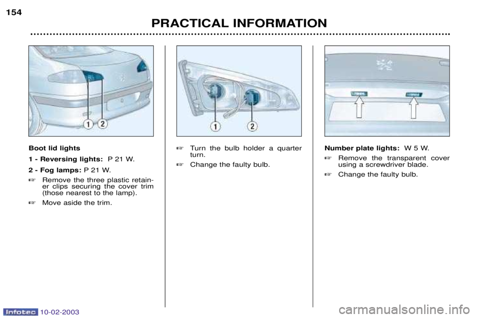
Boot lid lights 1 - Reversing lights: P 21 W.
2 - Fog lamps: P 21 W.
� Remove the three plastic retain- er clips securing the cover trim(those nearest to the lamp).
� Move aside the trim. �
Turn the bulb holder a quarterturn.
� Change the faulty bulb. Number plate lights:
W 5 W.
� Remove the transparent coverusing a screwdriver blade.
� Change the faulty bulb.
Page 167 of 183
PRACTICAL INFORMATION155
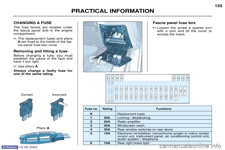
Correct Incorrect
Pliers A
CHANGING A FUSE The fuse boxes are located under the fascia panel and in the enginecompartment.
� The replacement fuses and pliersAare fixed to the inside of the fas-
cia panel fuse box cover.
Removing and fitting a fuse Before changing a fuse, you must establish the cause of the fault andhave it put right. � Use pliers A.
Always change a faulty fuse for one of the same rating. Fascia panel fuse box
� Loosen the screw a quarter turnwith a coin and tilt the cover toaccess the fuses.
Fuse no. Rating Functions R Replacement fuses.
1 30A Locking / deadlocking.
2 20A Radio amplifier.
3 30A Windscreen wash.
4 30A Rear window switches on rear doors.
5 15A Electronic immobiliser, monochrome screen or colour screen control unit, instrument panel, air conditioning control unit,
audio system / telephone.
6 10A Rear right brake light.
10-02-2003
Page 169 of 183
.
13* 20")
10-02-2003
Fuse N¡ RatingFunctions
10* 20 AAutomatic headlamp lighting control unit.
11* 70 A Built-in systems interface.
12* 70 A Ignition supply (+ve accessories / ignition controlled +ve).
13* 20 A Automatic headlamp lighting control unit.
14 15 A Double injection relay supply.
15* - Not used.
16* - Not used.
17* 30 A ESP hydraulic unit.
18 30 A Ignition supply (+ starter).
19 20 A Variable suspension control unit.
20 10 A Fan unit relay - Cruise control safety switch - Manual gearbox clutch switch - Manual gearbox reversing lights switch or automatic gearbox multi-function switch -
Automatic headlamp lighting control unit - Vehicle speed sensor - Coolant level sensor -
Water in diesel sensor - Power switch control unit relay.
21 5 A Automatic gearbox control unit - Automatic gearbox multi-function switch.
22 25 A ESP control unit.
23 15 A Diesel heating.
24 5 A Engine management control unit Ð Dual control control unit.
25 10 A Fuel pump.
26 30 A Driver's seat memory control unit.
27 25 A Double injection relay supply.
28 10 A Throttle housing de-icing resistor, Intake pilot solenoid valve - Flow meter - Piston de-activator injectionpump - Oil heating.
29 30 A Air pump, diesel additive control unit - Diesel additive injector.
30 - Cannot be used.
31 5 A Automatic gearbox shift lock.
32 10 A ESP or ABS control unit.
33 15 A Automatic gearbox control unit - Automatic gearbox multi-function switch (except reversing lights) - Automaticgearbox sequential control.
34 5 A Oxygen sensors - Exhaust gas recirculation solenoid valve, Exhaust gas recirculation throttle solenoid valve -
Turbo pressure regulation solenoid valve.
PRACTICAL INFORMATION
158
Page 170 of 183
PRACTICAL INFORMATION155
Correct Incorrect
Pliers A
CHANGING A FUSE The fuse boxes are located under the fascia panel and in the enginecompartment.
� The replacement fuses and pliersAare fixed to the inside of the fas-
cia panel fuse box cover.
Removing and fitting a fuse Before changing a fuse, you must establish the cause of the fault andhave it put right. � Use pliers A.
Always change a faulty fuse for one of the same rating. Fascia panel fuse box
� Loosen the screw a quarter turnwith a coin and tilt the cover toaccess the fuses.
Fuse no. Rating Functions R Replacement fuses.
1 30A Locking / deadlocking.
2 20A Radio amplifier.
3 30A Windscreen wash.
4 30A Rear window switches on rear doors.
5 15A Electronic immobiliser, monochrome screen or colour screen control unit, instrument panel, air conditioning control unit,
audio system / telephone.
6 10A Rear right brake light.
10-02-2003
Page 171 of 183

10-02-2003
PRACTICAL INFORMATION
156
Fuse no. Rating Functions
7 10 A Switches, rear lighter illumination, front courtesy light, rear courtesy light, rear lighter, number plate lighting, headlamp height adjustment.
8 10 A Diagnostic connector, headlamp height adjustment control unit, HF locking receiver,
passenger compartment air temperature sensor, HF tyre under-inflation receiver.
9 20 A Headlamp wash.
10 20 A Glove box lighting, front lighter, front and rear courtesy light, electrochrome interior mirror,electric exterior mirrors.
11 5 A Control unit for automatic lighting of headlamps, air bags control unit, safety relay for automatic lighting of headlamps.
12 30 A Rear window switches on driver's pad, rear windows.
13 30 A Windscreen wiper.
14 15 A Not used.
15 15 A Driver's door pad, passenger's door pad.
16 15 A Rear lighter.
17 5 A Heated exterior mirrors.
18 15 A Rear left brake light, additional brake light.
19 10 A Parking assistance control unit, navigation control unit.
20 15 A Alarm siren, monochrome screen or colour screen control unit, HF receiver, audio system /telephone, monochrome or colour navigation control unit, diesel additive control unit.
21 15 A Dignostic connector, caravan socket, trailer sidelights relay.
22 15 A Diesel additive control unit, driver's seat memory control unit, driver's door pad, passenger's door pad.
23 30 A Driver's window, passenger's window, sunroof safety auto-reverse, passenger window swit-ch on driver's door pad andpassenger's door pad.
24 10 A Rear fog lamp.
25 40 A PARC shunt.
26 40 A Heated rear screen, radio aerial amplifier.
Page 173 of 183

10-02-2003
Ð Never disconnect a ter-minal when the engine is running.
Ð Never charge a battery without first disconnect-ing the terminals.
Ð Close the windows and sunroof fully before disconnecting the
battery.
Ð After every disconnection of the battery, switch on the ignitionand wait for 1 minute beforestarting, to allow the electronicsystems to be initialised. How-
ever, if slight difficulties areexperienced after this, please
contact a PEUGEOT dealer.
PRACTICAL INFORMATION
160
BATTERY
Vehicles fitted with a single battery
To charge the battery using a battery charger:� Remove the style cover to gain access to the battery,
� Disconnect the battery.
Follow the instructions for use given by the battery charger manufacturer,
� Reconnect the battery, starting with the negative (-) terminal,
� Check that the terminals and connectors are clean. If they are covered with sulphate (whitish or greenish deposit), disconnect them and clean them,
� Refit the style cover.
To start the vehicle from another battery: � Remove the style cover to gain access to the battery,
� Connect the red cable to the positive (+) terminals of both batteries,
� Connect one end of the green or black cable to the negative (-) terminal of the
slave battery,
� Connect the other end of the green or black cable to an earth point on the
broken down vehicle, as far as possible from the battery,
� Start the engine and let it run,
� Wait for the engine to return to idle then disconnect the cables,
� Refit the style cover.
If electrical work is carried
out, disconnect the starter battery.
It is advisable to disconnect the battery if the vehicle is
not to be used for a period of more than one month.
Page 176 of 183

10-02-2003
TOWING A TRAILER,
CARAVAN, BOAT ETC...
Only use original PEUGEOT tow bars which have been tested andapproved from the design stage ofyour vehicle. The tow bar must be fitted by a
PEUGEOT dealer. Driving advice Distribution of loads: distribute the
load in the trailer so that the heaviest loads are as close as possible to theaxle and the nose weight is close tothe maximum authorised without,
however, exceeding it. Cooling: towing a trailer on a slope
increases the coolant temperature.As the fan is electronically controlled, its cooling capacity is not dependenton the engine speed.
On the contrary, use a high gear to lower the engine speed, and reduceyour speed. In all cases, pay attention to thecoolant temperature. Note:
in certain cases of particularly
arduous use (towing the maximum load up a steep slope in high tem-peratures), the engine automatically
limits its power. In this case, cutting
off the air conditioning allows theengine power to be recovered, andtherefore the towing speed to be sig-nificantly increased (approximately12mph [20 km/h] more). If the coolant temperature warning light comes on, stop the vehicle and
switch off the engine as soon aspossible.
Tyres: check the tyre pressures of
the towing vehicle and of the trailer, observing the recommended pres-sure. Brakes: towing increases the brak-
ing distance. Drive at a moderate speed, change down early and brake
gradually. Side wind: sensitivity to side wind is
increased. Drive smoothly and at a moderate speed. Lighting Manual adjustmentAdjust your headlamps so as not to dazzle other road users (see sectionon ''Manual adjustment of head-lamps''). Check the electrical sig-
nalling of the trailer. Automatic beam correction For vehicles with Xenon bulbs, this system automatically corrects theheight of the beam, whatever the
load of the vehicle. The driver is thenassured of having optimum lightingand not causing a nuisance to otherroad users. In cases of malfunction, the driver is alerted by means of the warning lighton the instrument panel. In this situation the system adjusts your headlamps to the low position.
PRACTICAL INFORMATION
163