Page 1781 of 4179
![NISSAN X-TRAIL 2003 Service Repair Manual DTC P1212 TCS COMMUNICATION LINE
EC-1403
[YD (WITHOUT EURO-OBD)]
C
D
E
F
G
H
I
J
K
L
MA
EC
DTC P1212 TCS COMMUNICATION LINEPFP:47850
DescriptionEBS0123D
NOTE:
If DTC P1212 is displayed with DTC U100](/manual-img/5/57404/w960_57404-1780.png "NISSAN X-TRAIL 2003 Service Repair Manual DTC P1212 TCS COMMUNICATION LINE
EC-1403
[YD (WITHOUT EURO-OBD)]
C
D
E
F
G
H
I
J
K
L
MA
EC
DTC P1212 TCS COMMUNICATION LINEPFP:47850
DescriptionEBS0123D
NOTE:
If DTC P1212 is displayed with DTC U100")
DTC P1212 TCS COMMUNICATION LINE
EC-1403
[YD (WITHOUT EURO-OBD)]
C
D
E
F
G
H
I
J
K
L
MA
EC
DTC P1212 TCS COMMUNICATION LINEPFP:47850
DescriptionEBS0123D
NOTE:
If DTC P1212 is displayed with DTC U1000, first perform the trouble diagnosis for DTC U1000. Refer to
EC-1268, "
DTC U1000 CAN COMMUNICATION LINE" .
This CAN communication line is used to control the smooth engine operation during the TCS operation. Pulse
signals are exchanged between ECM and ESP/TCS/ABS control unit.
Be sure to erase the malfunction information such as DTC not only for ESP/TCS/ABS control unit but
also for ECM after TCS related repair.
On Board Diagnosis LogicEBS0123E
The MI will not light up for this self-diagnosis.
DTC Confirmation ProcedureEBS0123F
NOTE:
If DTC Confirmation Procedure has been previously conducted, always turn ignition switch OFF and wait at
least 10 seconds before conducting the next test.
WITH CONSULT-II
1. Turn ignition switch ON.
2. Select “DATA MONITOR” mode with CONSULT-II.
3. Wait at least 5 seconds.
4. If DTC is detected, go to EC-1403, "
Diagnostic Procedure" .
Diagnostic ProcedureEBS0123G
1. CHECK ESP/TCS/ABS CONTROL UNIT FUNCTION
Refer to BRC-58, "
TROUBLE DIAGNOSIS" (Models with ESP system) or BRC-11, "TROUBLE DIAGNOSIS"
(Models without ESP system).
>>INSPECTION END
DTC No. Trouble diagnosis name DTC detecting condition Possible cause
P1212 TCS communication lineECM can not receive the information from ESP/
TCS/ABS control unit continuously.
�Harness or connectors
(The CAN communication line is
open or shorted.)
�ESP/TCS/ABS control unit
�Dead (Weak) battery
SEF817Y
Page 1883 of 4179
FUEL LEVEL SENSOR UNIT, FUEL FILTER AND FUEL PUMP ASSEMBLY
FL-5
[QR]
C
D
E
F
G
H
I
J
K
L
MA
FL
6. Remove inspection hole cover for main and sub fuel level sen-
sor units by turning clips clockwise by 90 degrees.
7. Disconnect harness connector and fuel feed hose.
�Disconnect quick connector as follows:
–Hold the sides of connector, push in tabs and pull out tube.
–If connector and tube are stuck together, push and pull sev-
eral times until they start to move. Then disconnect them by
pulling.
PBIC2258E
KBIA0280E
SFE562A
Page 1884 of 4179
![NISSAN X-TRAIL 2003 Service Repair Manual FL-6
[QR]
FUEL LEVEL SENSOR UNIT, FUEL FILTER AND FUEL PUMP ASSEMBLY
CAUTION:
�Quick connector can be removed when the tabs are
completely depressed. Do not twist it more than neces-
sary.
�Do not u](/manual-img/5/57404/w960_57404-1883.png "NISSAN X-TRAIL 2003 Service Repair Manual FL-6
[QR]
FUEL LEVEL SENSOR UNIT, FUEL FILTER AND FUEL PUMP ASSEMBLY
CAUTION:
�Quick connector can be removed when the tabs are
completely depressed. Do not twist it more than neces-
sary.
�Do not u")
FL-6
[QR]
FUEL LEVEL SENSOR UNIT, FUEL FILTER AND FUEL PUMP ASSEMBLY
CAUTION:
�Quick connector can be removed when the tabs are
completely depressed. Do not twist it more than neces-
sary.
�Do not use any tools to disconnect quick connector.
�Keep resin tube away from heat. Be especially careful
when welding near the tube.
�Prevent acid liquid such as battery electrolyte, etc.
from getting on resin tube.
�Do not bend or twist resin tube during installation and
disconnection.
�Do not remove the remaining retainer on hard tube (or
equivalent) except when resin tube or retainer is
replaced.
�When resin tube or hard tube (or equivalent) is
replaced, also replace retainer with a new one.
�To keep the connecting portion clean and to avoid
damage and foreign materials, cover them completely
with plastic bags or something similar.
8. Using a fuel tank lock ring wrench (commercial service tool),
remove lock ring.
9. Remove main fuel level sensor unit, fuel filter and fuel pump assembly, and sub fuel level sensor unit as
follows.
CAUTION:
�Do not bend float arm during removal.
�Avoid impacts such as falling when handling components.Retainer color: Green
SBIA0504E
PBIC0163E
PBIC0240E
Page 1885 of 4179
![NISSAN X-TRAIL 2003 Service Repair Manual FUEL LEVEL SENSOR UNIT, FUEL FILTER AND FUEL PUMP ASSEMBLY
FL-7
[QR]
C
D
E
F
G
H
I
J
K
L
MA
FL
a. Removal of main fuel level sensor unit, fuel filter and fuel pump
assembly:
i. Raise main fuel level](/manual-img/5/57404/w960_57404-1884.png "NISSAN X-TRAIL 2003 Service Repair Manual FUEL LEVEL SENSOR UNIT, FUEL FILTER AND FUEL PUMP ASSEMBLY
FL-7
[QR]
C
D
E
F
G
H
I
J
K
L
MA
FL
a. Removal of main fuel level sensor unit, fuel filter and fuel pump
assembly:
i. Raise main fuel level")
FUEL LEVEL SENSOR UNIT, FUEL FILTER AND FUEL PUMP ASSEMBLY
FL-7
[QR]
C
D
E
F
G
H
I
J
K
L
MA
FL
a. Removal of main fuel level sensor unit, fuel filter and fuel pump
assembly:
i. Raise main fuel level sensor unit, fuel filter and fuel pump
assembly, and disconnect jet pump.
ii. Leave jet pump on fuel tank with fuel hose.
CAUTION:
Do not disconnect jet pump and fuel hose.
iii. If necessary, remove chamber from the bottom of fuel tank by
sliding toward the rear of the vehicle.
b. Removal of sub fuel level sensor unit:
i. Raise and release sub fuel level sensor unit to remove.
ii. If necessary, remove jet pump inlet from the bottom of fuel tank by pinching tabs.
CAUTION:
Do not separate jet pump inlet and fuel hose.
INSPECTION AFTER REMOVAL
Make sure that fuel pump strainer is free from foreign materials. If any are found, remove them.
INSTALLATION
Note the following, and install in the reverse order of removal.
Chamber and Jet Pump
When installing chamber and jet pump, insert them fully until a click
sound of full stopper engagement is heard (Ditto for jet pump inlet).
Main and Sub Fuel Level Sensor Unit
Install fuel level sensor unit with positioning mark (triangular protru-
sion) facing between two carved lines on fuel tank. (Figure shows left
side of fuel tank.)
NOTE:
On right side of fuel tank, there are three carved lines on fuel tank.
Set mating mark between two outer carved lines.
Quick Connector
Connect quick connector as follows:
1. Check the connection for damage and foreign materials.
2. Align the connector with the tube, then insert the connector straight into the tube until a click sound is
heard.
3. After connecting, make sure that the connection is secure by following method.
�Visually confirm that the two tabs are connected to the connector.
KBIA0281E
KBIA0302E
KBIA0282E
Page 1887 of 4179
![NISSAN X-TRAIL 2003 Service Repair Manual FUEL LEVEL SENSOR UNIT, FUEL FILTER AND FUEL PUMP ASSEMBLY
FL-9
[QR]
C
D
E
F
G
H
I
J
K
L
MA
FL
a. Using a screwdriver, separate the snap fit portion of bracket in
numerical order as shown in the fig](/manual-img/5/57404/w960_57404-1886.png "NISSAN X-TRAIL 2003 Service Repair Manual FUEL LEVEL SENSOR UNIT, FUEL FILTER AND FUEL PUMP ASSEMBLY
FL-9
[QR]
C
D
E
F
G
H
I
J
K
L
MA
FL
a. Using a screwdriver, separate the snap fit portion of bracket in
numerical order as shown in the fig")
FUEL LEVEL SENSOR UNIT, FUEL FILTER AND FUEL PUMP ASSEMBLY
FL-9
[QR]
C
D
E
F
G
H
I
J
K
L
MA
FL
a. Using a screwdriver, separate the snap fit portion of bracket in
numerical order as shown in the figure.
CAUTION:
Put cloth or similar one on the edge of screwdriver not to
damage the inserted portion.
b. Pull out fuel pump, and disconnect harness connector.
2. Separate fuel filter and fuel level sensor unit as follows:
a. Fit a used O-ring into space between fuel level sensor unit and
fuel filter to release tabs.
NOTE:
For reference when reassembling, put a mating mark on outer
edges of fuel level sensor unit and fuel filter with some means
which cannot be erased by fuel.
b. Insert screwdriver to the gap between fuel filter and fuel level
sensor unit to separate them.
CAUTION:
Put cloth or similar one on the edge of screwdriver not to
damage the inserted portion.
3. Remove pressure regulator from fuel filter as follows:
a. Open and remove the clip.
b. Pull pressure regulator straight out during removal.
CAUTION:
�Avoid impacts such as falling during removal.
�Do not disassemble or adjust.
ASSEMBLY
Note the following, and assemble in the reverse order of disassembly.
�Install fuel filter and fuel pump with the tabs aligned. Make sure a click sound of secure engagement is
heard.
�Securely connect harness connector of fuel pump.
�Install pressure regulator O-ring.
CAUTION:
�When replacing, always use new O-ring.
�Handle it with bare hands. (Do not use gloves.)
�Visually check the O-ring, mounting parts and mating parts for foreign materials and flaws.
�Before installing, apply new engine oil.
�To avid damage, do not apply an excessive force (pulling or starching).
PBIC0242E
PBIC0243E
PBIC0244E
Page 1899 of 4179
![NISSAN X-TRAIL 2003 Service Repair Manual FUEL LEVEL SENSOR UNIT
FL-21
[YD22DDTi]
C
D
E
F
G
H
I
J
K
L
MA
FL
CAUTION:
�The quick connector can be removed when the tabs are
completely depressed. Do not twist it more than neces-
sary.
�Do not](/manual-img/5/57404/w960_57404-1898.png "NISSAN X-TRAIL 2003 Service Repair Manual FUEL LEVEL SENSOR UNIT
FL-21
[YD22DDTi]
C
D
E
F
G
H
I
J
K
L
MA
FL
CAUTION:
�The quick connector can be removed when the tabs are
completely depressed. Do not twist it more than neces-
sary.
�Do not")
FUEL LEVEL SENSOR UNIT
FL-21
[YD22DDTi]
C
D
E
F
G
H
I
J
K
L
MA
FL
CAUTION:
�The quick connector can be removed when the tabs are
completely depressed. Do not twist it more than neces-
sary.
�Do not use any tools to disconnect quick connector.
�Keep the resin tube away from heat. Be especially careful
when welding near the tube.
�Prevent acid liquid such as battery electrolyte etc. from
getting on resin tube.
�Do not bend or twist the tube during installation and
removal.
�Do not remove the remaining retainer on hard tube (or
equivalent) except when resin tube or retainer is
replaced.
�When resin tube or fuel level sensor unit is replaced, also
replace retainer with a new one.
�To keep clean the connecting portion and to avoid dam-
age and foreign materials, cover them completely with
plastic bags or something similar.
8. Using a fuel tank lock ring wrench (commercial service tool),
remove the lock ring.
9. Remove main fuel level sensor unit (Left hand) and sub fuel level sensor unit (Right hand).
CAUTION:
�Do not bend the float arm during removal.
�Avoid impacts such as falling when handling components.
Left hand (main fuel level sensor unit):
�If necessary, remove the chamber from the bottom of the fuel tank.
�Remove the chamber by sliding toward the rear of the vehicle.Retainer color : Green (Fuel feed tube)
: Gray (Fuel return tube)
SBIA0504E
PBIC0163E
PBIC0240E
Page 1900 of 4179
![NISSAN X-TRAIL 2003 Service Repair Manual FL-22
[YD22DDTi]
FUEL LEVEL SENSOR UNIT
INSPECTION AFTER REMOVAL
Make sure fuel pump strainer is free from foreign materials. If any are found, remove them.
INSTALLATION
Note the following, and inst](/manual-img/5/57404/w960_57404-1899.png "NISSAN X-TRAIL 2003 Service Repair Manual FL-22
[YD22DDTi]
FUEL LEVEL SENSOR UNIT
INSPECTION AFTER REMOVAL
Make sure fuel pump strainer is free from foreign materials. If any are found, remove them.
INSTALLATION
Note the following, and inst")
FL-22
[YD22DDTi]
FUEL LEVEL SENSOR UNIT
INSPECTION AFTER REMOVAL
Make sure fuel pump strainer is free from foreign materials. If any are found, remove them.
INSTALLATION
Note the following, and install in the reverse order of removal.
�Connect quick connector as follows.
1. Check connection for damage and foreign materials.
2. Align the connector with the tube, then insert connector straight into tube until a click is heard.
3. After connecting, make sure that the connection is secure by following the steps below.
�Visually confirm that the two tabs are connected to connector.
�Pull the tube and connector to make sure they are securely
connected.
�Install fuel level sensor unit with mating mark (triangular pro-
trusion) facing between two carved lines on fuel tank. (Figure
shows left side of fuel tank.)
NOTE:
On right side of fuel tank, there are three carved lines on fuel
tank. Set mating mark between two outer carved lines.
�Install inspection hole cover with the front mark (arrow) facing front of vehicle (both for RH and LH).
INSPECTION AFTER INSTALLATION
Make sure there is no fuel leakage at connections in the following steps.
�Start engine and rev it up and make sure there is no fuel leakage at connections.
PBIC1653E
PBIC2032E
Page 1918 of 4179
CL-4
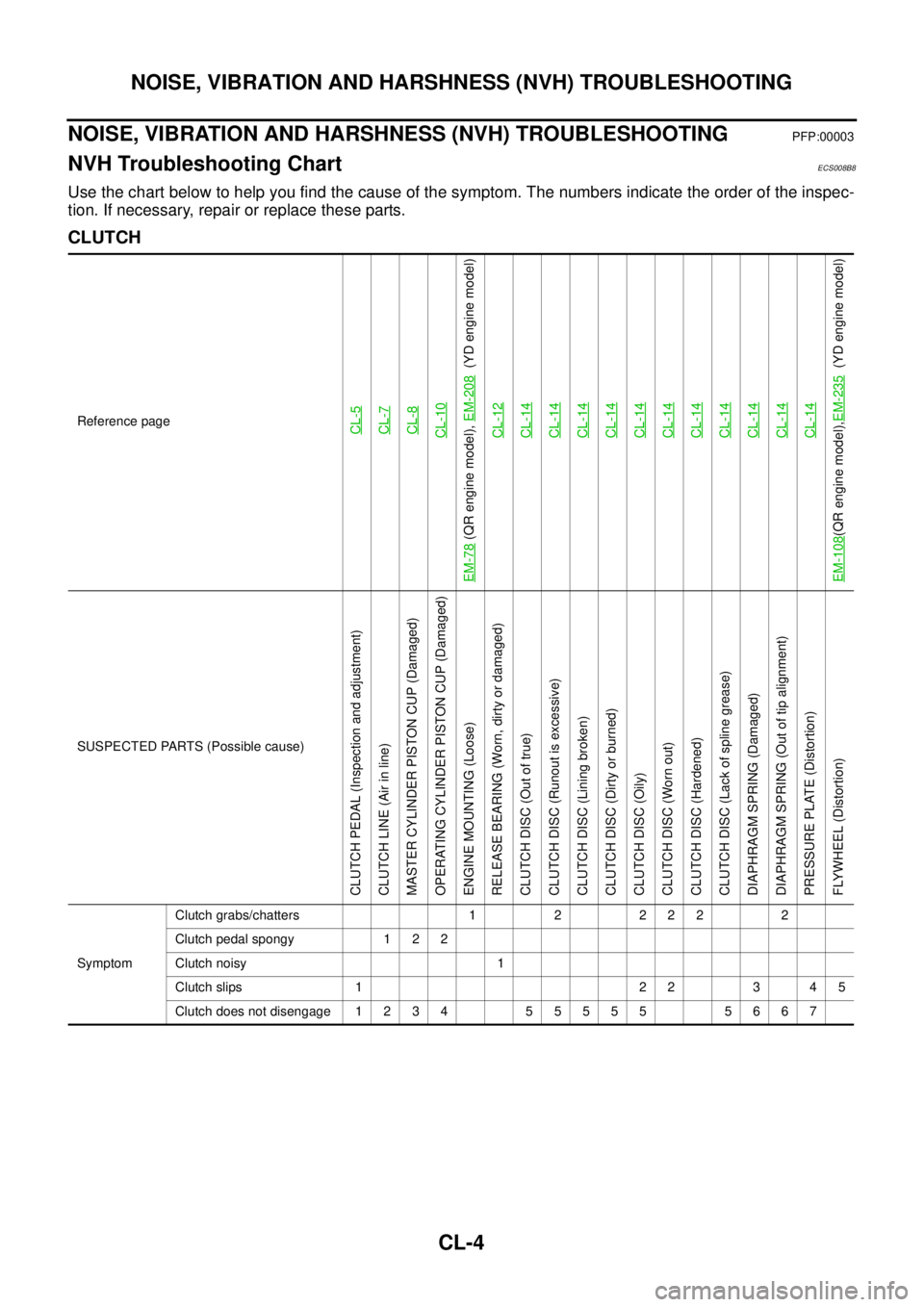
NOISE, VIBRATION AND HARSHNESS (NVH) TROUBLESHOOTING
NOISE, VIBRATION AND HARSHNESS (NVH) TROUBLESHOOTINGPFP:00003
NVH Troubleshooting ChartECS008B8
Use the chart below to help you find the cause of the symptom. The numbers indicate the order of the inspec-
tion. If necessary, repair or replace these parts.
CLUTCH
Reference pageCL-5CL-7CL-8CL-10
EM-78
(QR engine model), EM-208
(YD engine model)
CL-12
CL-14CL-14CL-14CL-14CL-14CL-14CL-14CL-14CL-14CL-14CL-14
EM-108
(QR engine model),EM-235
(YD engine model)
SUSPECTED PARTS (Possible cause)
CLUTCH PEDAL (Inspection and adjustment)
CLUTCH LINE (Air in line)
MASTER CYLINDER PISTON CUP (Damaged)
OPERATING CYLINDER PISTON CUP (Damaged)
ENGINE MOUNTING (Loose)
RELEASE BEARING (Worn, dirty or damaged)
CLUTCH DISC (Out of true)
CLUTCH DISC (Runout is excessive)
CLUTCH DISC (Lining broken)
CLUTCH DISC (Dirty or burned)
CLUTCH DISC (Oily)
CLUTCH DISC (Worn out)
CLUTCH DISC (Hardened)
CLUTCH DISC (Lack of spline grease)
DIAPHRAGM SPRING (Damaged)
DIAPHRAGM SPRING (Out of tip alignment)
PRESSURE PLATE (Distortion)
FLYWHEEL (Distortion)
SymptomClutch grabs/chatters 1 2 2 2 2 2
Clutch pedal spongy 1 2 2
Clutch noisy 1
Clutch slips 1 2 2 3 4 5
Clutch does not disengage 1 2 3 4 5 5 5 5 5 5 6 6 7
![NISSAN X-TRAIL 2003 Service Repair Manual FUEL LEVEL SENSOR UNIT, FUEL FILTER AND FUEL PUMP ASSEMBLY
FL-5
[QR]
C
D
E
F
G
H
I
J
K
L
MA
FL
6. Remove inspection hole cover for main and sub fuel level sen-
sor units by turning clips clockwise b](/manual-img/5/57404/w960_57404-1882.png "NISSAN X-TRAIL 2003 Service Repair Manual FUEL LEVEL SENSOR UNIT, FUEL FILTER AND FUEL PUMP ASSEMBLY
FL-5
[QR]
C
D
E
F
G
H
I
J
K
L
MA
FL
6. Remove inspection hole cover for main and sub fuel level sen-
sor units by turning clips clockwise b")