Page 3300 of 4179

EI-2 DOOR FINISHER ...................................................... 32
Removal and Installation ........................................ 32
FRONT AND REAR ............................................. 32
BACK DOOR TRIM ................................................... 34
Removal and Installation ........................................ 34
REMOVAL ........................................................... 34
INSTALLATION .................................................... 34
BODY SIDE TRIM ..................................................... 35
Removal and Installation ........................................ 35
CENTER PILLAR LOWER GARNISH ................. 36
CENTER PILLAR UPPER GARNISH .................. 36
LUGGAGE SIDE LOWER FINISHER ................. 36
REAR PILLAR FINISHER ................................... 36
DASHBOARD SIDE FINISHER ........................... 36
BODY SIDE WELT .............................................. 36FLOOR TRIM ............................................................. 38
Removal and Installation ......................................... 38
REMOVAL ............................................................ 38
INSTALLATION .................................................... 38
HEADLINING ............................................................. 39
Removal and Installation ......................................... 39
REMOVAL ............................................................ 39
INSTALLATION .................................................... 40
Page 3329 of 4179
LICENSE LAMP FINISHER
EI-31
C
D
E
F
G
H
J
K
L
MA
B
EI
LICENSE LAMP FINISHERPFP:84810
Removal and InstallationEIS001NV
REMOVAL
1. Remove back door finisher. Refer to EI-34, "Removal and Installation" .
2. Remove license plate lamp. Refer to LT- 5 1 , "
LICENSE PLATE LAMP" .
3. Remove license lamp finisher mounting nuts and clips. Then remove finisher.
INSTALLATION
Installation is in the reverse order of removal.
1. License lamp finisher
SIIA0220E
Page 3332 of 4179
EI-34
BACK DOOR TRIM
BACK DOOR TRIMPFP:90900
Removal and InstallationEIS000NA
REMOVAL
1. Remove clips of back door trim.
2. Remove back door trim.
INSTALLATION
Installation is in the reverse order of removal.
NOTE:
�Insert a clip driver or clip clamp remover into the part shown by
the arrow (between the clips and the body side panel). Remove
clips.
�When installing, confirm clips are surely aligned with the holes
on the body side panel, then press in.
SIIA0221E
PIIA0527E
Page 3333 of 4179
BODY SIDE TRIM
EI-35
C
D
E
F
G
H
J
K
L
MA
B
EI
BODY SIDE TRIMPFP:76913
Removal and InstallationEIS000NB
PIIB0591E
1. Front pillar garnish 2. Dashboard side finisher 3. Front body side welt
4. Front kick panel 5. Center pillar upper garnish 6. Center pillar lower garnish
7. Rear body side welt 8. Rear kick panel 9. Rear pillar finisher
10. Luggage side lower finisher 11. Front luggage floorboard 12. Luggage floor rear spacer (right)
13. Luggage floor rear spacer (center) 14. Luggage floor rear spacer (left) 15. Luggage floorboard (right)
16. Rear luggage floorboard 17. Luggage floorboard (left) 18. Luggage rear plate
19. Back door weather strip 20. Hook 21. Net
22. Tonneau cover
Page 3338 of 4179

EI-40
HEADLINING
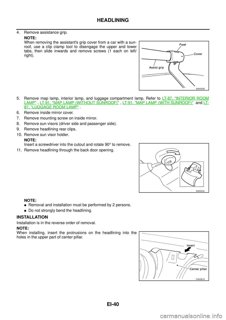
4. Remove assistance grip.
NOTE:
When removing the assistant's grip cover from a car with a sun-
roof, use a clip clamp tool to disengage the upper and lower
tabs, then slide inwards and remove screws (1 each on left/
right).
5. Remove map lamp, interior lamp, and luggage compartment lamp. Refer to LT- 8 7 , "
INTERIOR ROOM
LAMP" , LT- 9 1 , "MAP LAMP (WITHOUT SUNROOF)" , LT- 9 1 , "MAP LAMP (WITH SUNROOF)" and LT-
87, "LUGGAGE ROOM LAMP" .
6. Remove inside mirror cover.
7. Remove mounting screw on inside mirror.
8. Remove sun visors (driver side and passenger side).
9. Remove headlining rear clips.
10. Remove sun visor holder.
NOTE:
Insert a screwdriver into the cutout and rotate 90° to remove.
11. Remove headlining through the back door opening.
NOTE:
�Removal and installation must be performed by 2 persons.
�Do not strongly bend the headlining.
INSTALLATION
Installation is in the reverse order of removal.
NOTE:
When installing, insert the protrusions on the headlining into the
holes in the upper part of center pillar.
SIIA0052E
SIIA0224J
PIIA0561E
Page 3350 of 4179
IP-12
INSTRUMENT PANEL ASSEMBLY
[ ]: The number shows the removal order.
REMOVAL
Front Speaker Grille (LH/RH)
1. Insert a remover into front speaker grille door side edge, and
then disengage pawls and clips.
2. Pull forward and remove.
Cluster Lid A
Disengage clips by pulling cluster lid A frontward to remove.
CAUTION:
During removal or installation, use shop cloth to protect sur-
rounding area from damage.
Combination Meter
1. Remove screw.
2. Disconnect connector on back and remove combination meter.
CAUTION:
During removal or installation, use shop cloth to protect
surrounding area from damage.
Instrument panelIP-17[25]
Side ventilator grille (LH/RH)ATC-138
[26]
Cup holderIP-18
[27] Components Parts Location Refer toInstrument
panelCombination
meterDisplay unit Audio Console
PIIA9899E
PIIA7393E
PIIA7394JPIIA7394E
Page 3361 of 4179

SE-1
SEAT
I BODY
CONTENTS
C
D
E
F
G
H
J
K
L
M
SECTION
A
B
SE
SEAT
PRECAUTIONS .......................................................... 2
Precautions for Supplemental Restraint System
(SRS) “AIR BAG” and “SEAT BELT PRE-TEN-
SIONER” .................................................................. 2
Service Notice .......................................................... 2
Precautions .............................................................. 2
PREPARATION ........................................................... 3
Commercial Service Tools ........................................ 3
SQUEAK AND RATTLE TROUBLE DIAGNOSES ..... 4
Work Flow ................................................................ 4
CUSTOMER INTERVIEW ..................................... 4
DUPLICATE THE NOISE AND TEST DRIVE ....... 5
CHECK RELATED SERVICE BULLETINS ........... 5
LOCATE THE NOISE AND IDENTIFY THE
ROOT CAUSE ...................................................... 5
REPAIR THE CAUSE ........................................... 5
CONFIRM THE REPAIR ....................................... 6
Generic Squeak and Rattle Troubleshooting ........... 6
INSTRUMENT PANEL .......................................... 6
CENTER CONSOLE ............................................. 6
DOORS ................................................................. 6
TRUNK .................................................................. 7
SUNROOF/HEADLINING ..................................... 7
SEATS ................................................................... 7
UNDERHOOD ....................................................... 7
Diagnostic Worksheet .............................................. 8
POWER SEAT .......................................................... 10
Schematic .............................................................. 10
Wiring Diagram—SEAT— /For LHD Models ........... 11
Wiring Diagram—SEAT— /For RHD Models ......... 14
HEATED SEAT ......................................................... 17
Schematic .............................................................. 17Wiring Diagram—H/SEAT— /For LHD Models ....... 18
Wiring Diagram—H/SEAT—/For RHD Models ....... 21
FRONT SEAT ............................................................ 24
Component Parts Drawing ..................................... 24
MANUAL SEAT ................................................... 24
POWER SEAT ..................................................... 25
Removal and Installation ........................................ 26
REMOVAL ........................................................... 26
INSTALLATION ................................................... 26
Disassembly and Assembly of Seatback ................ 26
SEATBACK TRIM (SIDE AIR BAG EQUIPPED
AND GENUINE LEATHER SEAT) ....................... 26
SEATBACK TRIM [WITHOUT SIDE AIR BAG
(EXCEPT GENUINE LEATHER SEAT)] .............. 28
Disassembly and Assembly of Seat Cushion Trim ... 29
MANUAL SEAT ................................................... 29
Disassembly and Assembly of Seat Cushion Trim ... 30
POWER SEAT ..................................................... 30
REAR SEAT .............................................................. 31
Component Parts Drawing ..................................... 31
STANDARD SEAT ............................................... 31
SEAT WITH ARMREST ....................................... 32
Removal and Installation ........................................ 33
SEAT CUSHION .................................................. 33
SEATBACK .......................................................... 33
REAR SEAT STRIKER (SIDE) ............................ 34
REAR SEAT CENTER BRACKET ....................... 34
REAR SEAT STRIKER (FLOOR) ........................ 34
Disassembly and Assembly .................................... 34
REAR SEATBACK LOCK KNOB ......................... 34
ARMREST ........................................................... 34
Page 3451 of 4179

TROUBLE DIAGNOSIS
ATC-55
C
D
E
F
G
H
I
K
L
MA
B
AT C
Auto Amp. Terminals and Reference ValueEJS004GS
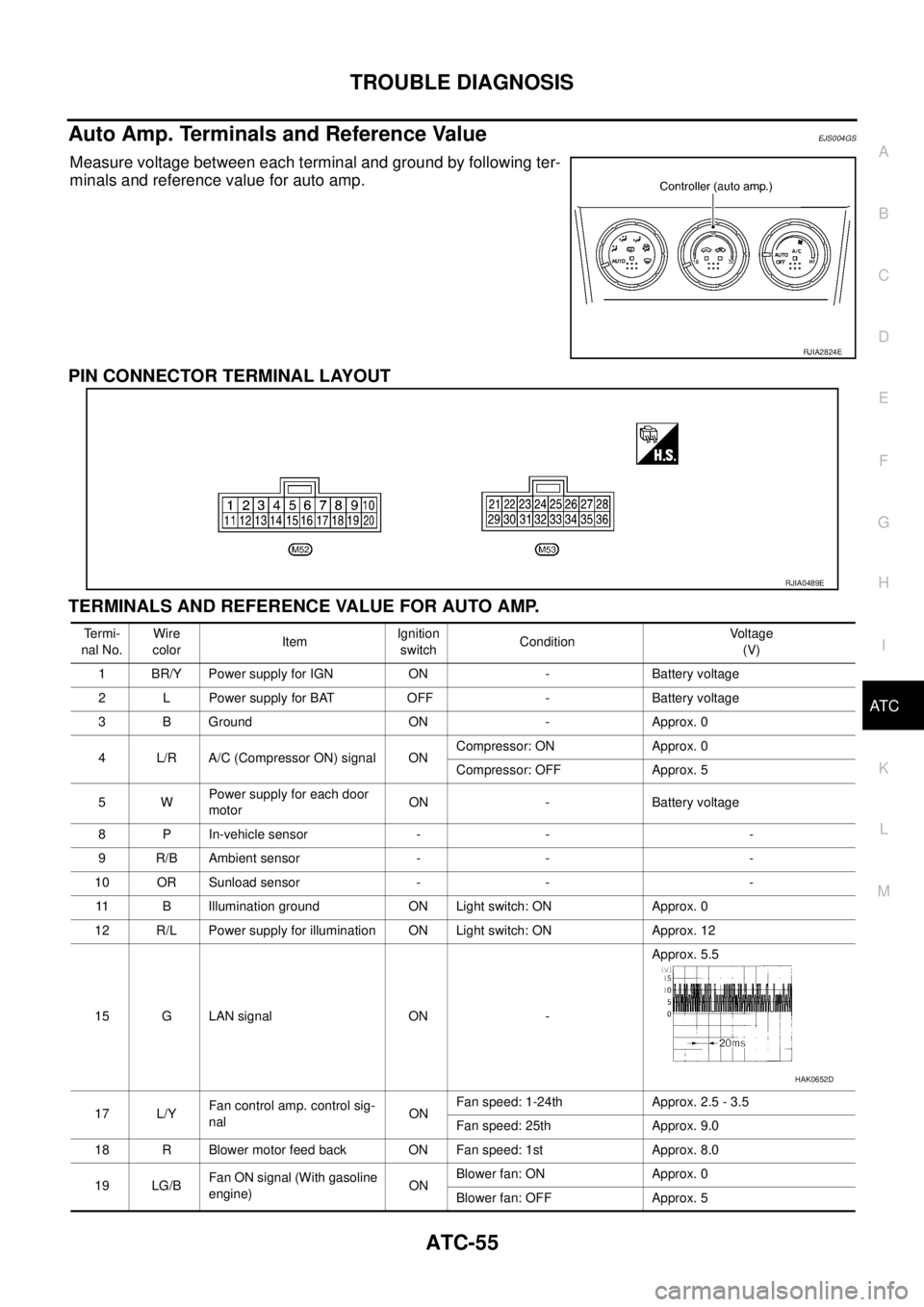
Measure voltage between each terminal and ground by following ter-
minals and reference value for auto amp.
PIN CONNECTOR TERMINAL LAYOUT
TERMINALS AND REFERENCE VALUE FOR AUTO AMP.
RJIA2824E
RJIA0489E
Te r m i -
nal No.Wire
colorItemIgnition
switchConditionVoltage
(V)
1 BR/Y Power supply for IGN ON - Battery voltage
2 L Power supply for BAT OFF - Battery voltage
3 B Ground ON - Approx. 0
4 L/R A/C (Compressor ON) signal ONCompressor: ON Approx. 0
Compressor: OFF Approx. 5
5WPower supply for each door
motorON - Battery voltage
8 P In-vehicle sensor - - -
9 R/B Ambient sensor - - -
10 OR Sunload sensor - - -
11 B Illumination ground ON Light switch: ON Approx. 0
12 R/L Power supply for illumination ON Light switch: ON Approx. 12
15 G LAN signal ON -Approx. 5.5
17 L/YFan control amp. control sig-
nalONFan speed: 1-24th Approx. 2.5 - 3.5
Fan speed: 25th Approx. 9.0
18 R Blower motor feed back ON Fan speed: 1st Approx. 8.0
19 LG/BFan ON signal (With gasoline
engine)ONBlower fan: ON Approx. 0
Blower fan: OFF Approx. 5
HAK0652D