Page 880 of 4179
EC-502
[QR (WITHOUT EURO-OBD)]
ENGINE CONTROL SYSTEM
A/T MODELS WITHOUT ESP
System Diagram
Input/output Signal Chart
T: Transmit R: Receive
PKIA6457E
Signals ECM TCMABS actuator
and electric unit
(control unit)4WD control
unitCombination
meter
Stop lamp switch signalRT
TR
P·N range signal R T
A/T position indicator lamp signal T R
Overdrive control switch signal R T
O/D OFF indicator signal T R
Closed throttle position signal T R
Wide open throttle position signal T R
Engine speed signal T R R
Engine coolant temperature signal TR
Accelerator pedal position signal T R
Output shaft revolution signal R T
A/C compressor feedback signal TR
Vehicle speed signalTRR
RT
ABS warning lamp signal T R
4WD warning lamp signalTR
4WD mode indicator lamp signalTR
Parking brake switch signalRT
MI signal TR
Engine A/T integrated control signalTR
RT
A/T self-diagnosis signal R T
Page 881 of 4179
ENGINE CONTROL SYSTEM
EC-503
[QR (WITHOUT EURO-OBD)]
C
D
E
F
G
H
I
J
K
L
MA
EC
M/T MODELS WITH ESP
System Diagram
Input/output Signal Chart
T: Transmit R: Receive
*1: YD engine models only
*2: QR engine models only
PKIA6459E
Signals ECMESP/TCS/ABS
control unitSteering angle
sensor4WD control
unitCombination
meter
Stop lamp switch signal T R
Engine speed signal T R R R
Engine coolant temperature signal TR
Accelerator pedal position signal T R R
A/C switch signal*
1RT
A/C compressor feedback signal*
2TR
Vehicle speed signalTRR
RT
ABS warning lamp signal T R
Brake warning lamp signal T R
SLIP indicator lamp signal T R
ESP OFF indicator lamp signal T R
4WD warning lamp signalTR
4WD mode indicator lamp signalTR
Parking brake switch signalRT
MI signal TR
Glow indicator lamp signal*
1TR
Steering angle sensor signal R T
Page 882 of 4179
EC-504
[QR (WITHOUT EURO-OBD)]
ENGINE CONTROL SYSTEM
A/T MODELS WITH ESP
System Diagram
Input/output Signal Chart
T: Transmit R: Receive
PKIA6460E
Signals ECM TCMESP/TCS/
ABS control
unitSte ering
angle sensor4WD control
unitCombination
meter
Stop lamp switch signalRT
TR
P·N range signal R T
A/T position indicator lamp signal T R R
O/D OFF indicator signal T R
Overdrive control switch signal R T
Closed throttle position signal T R
Wide open throttle position signal T R
Engine speed signal T R R R
Engine coolant temperature signal TR
Accelerator pedal position signal T R R
Output shaft revolution signal R T
A/C compressor feedback signal TR
Vehicle speed signalTRR
RT
ABS warning lamp signal T R
Brake warning lamp signal T R
SLIP indicator lamp signal T R
ESP OFF indicator lamp signal T R
4WD warning lamp signalTR
4WD mode indicator lamp signalTR
Parking brake switch signalRT
MI signal TR
Steering angle sensor signal R T
Page 883 of 4179
ENGINE CONTROL SYSTEM
EC-505
[QR (WITHOUT EURO-OBD)]
C
D
E
F
G
H
I
J
K
L
MA
EC
Engine and A/T integratedTR
RT
A/T self-diagnosis signal R TSignals ECM TCMESP/TCS/
ABS control
unitSteering
angle sensor4WD control
unitCombination
meter
Page 1267 of 4179
ENGINE CONTROL SYSTEM
EC-889
[YD (WITH EURO-OBD)]
C
D
E
F
G
H
I
J
K
L
MA
EC
CAN COMMUNICATION UNIT
System diagram
Input/output signal chart
T: Transmit R: Receive
PKIA6459E
Signals ECMESP/TCS/ABS
control unitSteering angle
sensor4WD control
unitCombination
meter
Stop lamp switch signal T R
Engine speed signal T R R R
Engine coolant temperature signal TR
Accelerator pedal position signal T R R
A/C switch signal RT
Vehicle speed signalTRR
RT
ABS warning lamp signal T R
Brake warning lamp signal T R
SLIP indicator lamp signal T R
ESP OFF indicator lamp signal T R
4WD warning lamp signalTR
4WD mode indicator lamp signalTR
Parking brake switch signalRT
MI signal TR
Glow indicator lamp signal TR
Steering angle sensor signal R T
Page 1598 of 4179
EC-1220
[YD (WITHOUT EURO-OBD)]
ENGINE CONTROL SYSTEM
CAN COMMUNICATION UNIT
System diagram
Input/output signal chart
T: Transmit R: Receive
PKIA6459E
Signals ECMESP/TCS/ABS
control unitSteering angle
sensor4WD control
unitCombination
meter
Stop lamp switch signal T R
Engine speed signal T R R R
Engine coolant temperature signal TR
Accelerator pedal position signal T R R
A/C switch signal RT
Vehicle speed signalTRR
RT
ABS warning lamp signal T R
Brake warning lamp signal T R
SLIP indicator lamp signal T R
ESP OFF indicator lamp signal T R
4WD warning lamp signalTR
4WD mode indicator lamp signalTR
Parking brake switch signalRT
MI signal TR
Glow indicator lamp signal TR
Steering angle sensor signal R T
Page 1944 of 4179
MT-12
SIDE OIL SEAL
SIDE OIL SEALPFP:32113
Removal and InstallationECS008BT
REMOVAL
�Clutch housing side oil seal used on 4WD vehicles is attached to transfer. Be sure to replace it
when transfer is removed.
1. Remove drive shaft from transaxle. Refer to FAX-11, "
Removal and Installation" .
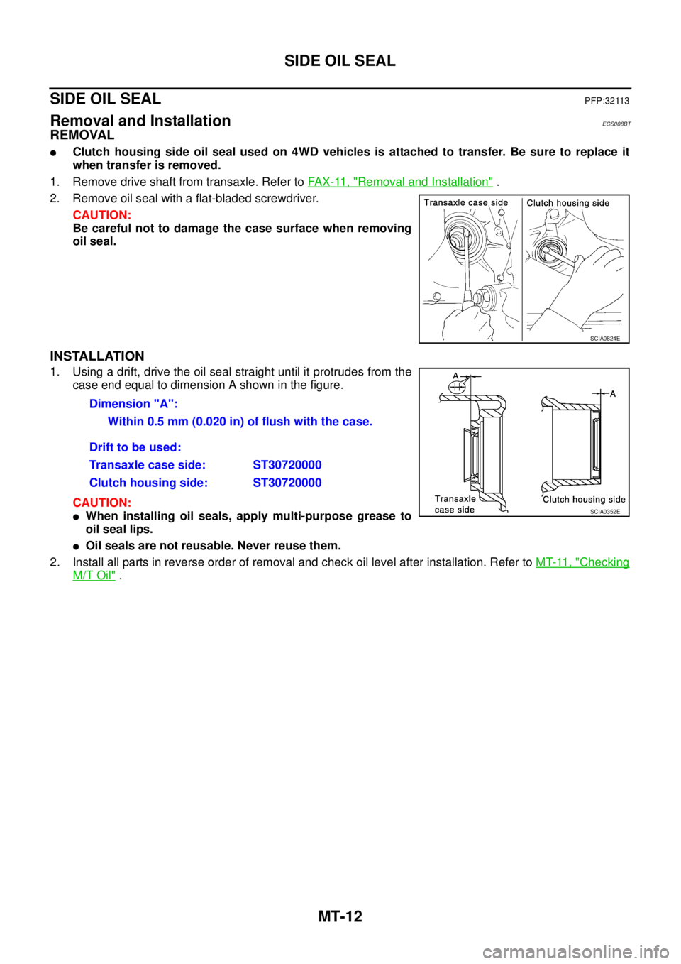
2. Remove oil seal with a flat-bladed screwdriver.
CAUTION:
Be careful not to damage the case surface when removing
oil seal.
INSTALLATION
1. Using a drift, drive the oil seal straight until it protrudes from the
case end equal to dimension A shown in the figure.
CAUTION:
�When installing oil seals, apply multi-purpose grease to
oil seal lips.
�Oil seals are not reusable. Never reuse them.
2. Install all parts in reverse order of removal and check oil level after installation. Refer to MT-11, "
Checking
M/T Oil" .
SCIA0824E
Dimension "A":
Within 0.5 mm (0.020 in) of flush with the case.
Drift to be used:
Transaxle case side: ST30720000
Clutch housing side: ST30720000
SCIA0352E
Page 2228 of 4179
![NISSAN X-TRAIL 2003 Service Repair Manual AT-192
[EURO-OBD]
DTC VEHICLE SPEED SENSOR MTR
DTC VEHICLE SPEED SENSOR MTRPFP:24814
DescriptionECS004SM
The vehicle speed sensor·MTR is built into the speedometer assem-
bly. The sensor functions](/manual-img/5/57404/w960_57404-2227.png "NISSAN X-TRAIL 2003 Service Repair Manual AT-192
[EURO-OBD]
DTC VEHICLE SPEED SENSOR MTR
DTC VEHICLE SPEED SENSOR MTRPFP:24814
DescriptionECS004SM
The vehicle speed sensor·MTR is built into the speedometer assem-
bly. The sensor functions")
AT-192
[EURO-OBD]
DTC VEHICLE SPEED SENSOR MTR
DTC VEHICLE SPEED SENSOR MTRPFP:24814
DescriptionECS004SM
The vehicle speed sensor·MTR is built into the speedometer assem-
bly. The sensor functions as an auxiliary device to the revolution sen-
sor when it is malfunctioning. The TCM will then use a signal sent
from the vehicle speed sensor·MTR.
On Board Diagnosis LogicECS00CUR
Possible CauseECS00CUS
Check the following items.
�Harness or connector
(The sensor circuit is open or shorted.)
�Vehicle speed sensor
DTC Confirmation ProcedureECS00CUT
CAUTION:
�Always drive vehicle at a safe speed.
�If conducting this “DTC Confirmation Procedure” again, always turn ignition switch OFF and wait
at least 5 seconds before continuing.
After the repair, perform the following procedure to confirm the malfunction is eliminated.
WITH CONSULT-II
1. Turn ignition switch ON and select “DATA MONITOR” mode for
“A/T” with CONSULT-II.
SCIA0716E
Diagnostic trouble code Malfunction is detected when... Check items (Possible cause)
: VHCL SPEED SEN·MTR
TCM does not receive the proper voltage
signal from the sensor.
�Harness or connectors
(The sensor circuit is open or shorted.)
�Combination meter
�4WD/ABS control unit : 2nd judgement flicker
SAT014K
![NISSAN X-TRAIL 2003 Service Repair Manual EC-502
[QR (WITHOUT EURO-OBD)]
ENGINE CONTROL SYSTEM
A/T MODELS WITHOUT ESP
System Diagram
Input/output Signal Chart
T: Transmit R: Receive
PKIA6457E
Signals ECM TCMABS actuator
and electric unit](/manual-img/5/57404/w960_57404-879.png "NISSAN X-TRAIL 2003 Service Repair Manual EC-502
[QR (WITHOUT EURO-OBD)]
ENGINE CONTROL SYSTEM
A/T MODELS WITHOUT ESP
System Diagram
Input/output Signal Chart
T: Transmit R: Receive
PKIA6457E
Signals ECM TCMABS actuator
and electric unit")
![NISSAN X-TRAIL 2003 Service Repair Manual ENGINE CONTROL SYSTEM
EC-503
[QR (WITHOUT EURO-OBD)]
C
D
E
F
G
H
I
J
K
L
MA
EC
M/T MODELS WITH ESP
System Diagram
Input/output Signal Chart
T: Transmit R: Receive
*1: YD engine models only
*2: QR](/manual-img/5/57404/w960_57404-880.png "NISSAN X-TRAIL 2003 Service Repair Manual ENGINE CONTROL SYSTEM
EC-503
[QR (WITHOUT EURO-OBD)]
C
D
E
F
G
H
I
J
K
L
MA
EC
M/T MODELS WITH ESP
System Diagram
Input/output Signal Chart
T: Transmit R: Receive
*1: YD engine models only
*2: QR")
![NISSAN X-TRAIL 2003 Service Repair Manual EC-504
[QR (WITHOUT EURO-OBD)]
ENGINE CONTROL SYSTEM
A/T MODELS WITH ESP
System Diagram
Input/output Signal Chart
T: Transmit R: Receive
PKIA6460E
Signals ECM TCMESP/TCS/
ABS control
unitSte erin](/manual-img/5/57404/w960_57404-881.png "NISSAN X-TRAIL 2003 Service Repair Manual EC-504
[QR (WITHOUT EURO-OBD)]
ENGINE CONTROL SYSTEM
A/T MODELS WITH ESP
System Diagram
Input/output Signal Chart
T: Transmit R: Receive
PKIA6460E
Signals ECM TCMESP/TCS/
ABS control
unitSte erin")
![NISSAN X-TRAIL 2003 Service Repair Manual ENGINE CONTROL SYSTEM
EC-505
[QR (WITHOUT EURO-OBD)]
C
D
E
F
G
H
I
J
K
L
MA
EC
Engine and A/T integratedTR
RT
A/T self-diagnosis signal R TSignals ECM TCMESP/TCS/
ABS control
unitSteering
angle sen](/manual-img/5/57404/w960_57404-882.png "NISSAN X-TRAIL 2003 Service Repair Manual ENGINE CONTROL SYSTEM
EC-505
[QR (WITHOUT EURO-OBD)]
C
D
E
F
G
H
I
J
K
L
MA
EC
Engine and A/T integratedTR
RT
A/T self-diagnosis signal R TSignals ECM TCMESP/TCS/
ABS control
unitSteering
angle sen")
![NISSAN X-TRAIL 2003 Service Repair Manual ENGINE CONTROL SYSTEM
EC-889
[YD (WITH EURO-OBD)]
C
D
E
F
G
H
I
J
K
L
MA
EC
CAN COMMUNICATION UNIT
System diagram
Input/output signal chart
T: Transmit R: Receive
PKIA6459E
Signals ECMESP/TCS/ABS](/manual-img/5/57404/w960_57404-1266.png "NISSAN X-TRAIL 2003 Service Repair Manual ENGINE CONTROL SYSTEM
EC-889
[YD (WITH EURO-OBD)]
C
D
E
F
G
H
I
J
K
L
MA
EC
CAN COMMUNICATION UNIT
System diagram
Input/output signal chart
T: Transmit R: Receive
PKIA6459E
Signals ECMESP/TCS/ABS")
![NISSAN X-TRAIL 2003 Service Repair Manual EC-1220
[YD (WITHOUT EURO-OBD)]
ENGINE CONTROL SYSTEM
CAN COMMUNICATION UNIT
System diagram
Input/output signal chart
T: Transmit R: Receive
PKIA6459E
Signals ECMESP/TCS/ABS
control unitSteering](/manual-img/5/57404/w960_57404-1597.png "NISSAN X-TRAIL 2003 Service Repair Manual EC-1220
[YD (WITHOUT EURO-OBD)]
ENGINE CONTROL SYSTEM
CAN COMMUNICATION UNIT
System diagram
Input/output signal chart
T: Transmit R: Receive
PKIA6459E
Signals ECMESP/TCS/ABS
control unitSteering")