Page 47 of 4179
IDENTIFICATION INFORMATION
GI-45
C
D
E
F
G
H
I
J
K
L
MB
GI
AUTOMATIC TRANSAXLE NUMBER
MANUAL TRANSAXLE NUMBER
Dimensions EAS000GF
Unit: mm (in)
Wheels & Tires EAS000GG
PAIA0008E
PAIA0009E
PAIA0010E
Overall length 4,455
Overall width 1,765
Overall height1,675 (Standard)
1,750 (With Rear spoiler or Roof rail with Driving light)
Front tread 1,530
Rear tread 1,530
Wheelbase 2,625
Conventional Spare
Road wheel/offset mm (in)15 × 6JJ Steel/40 (1.57)
16 × 6.5JJ Steel/Aluminum/40 (1.57)Conventional
Tire size215/70 R15
215/65 R16Conventional
Page 61 of 4179
PREPARATION
EM-9
[QR]
C
D
E
F
G
H
I
J
K
L
MA
EM
Commercial Service ToolsEBS00L7O
Tool nameDescription
Spark plug wrench Removing and installing spark plug
Pulley holderCrankshaft pulley removing and installing
Valve seat cutter set Finishing valve seat dimensions
TORX socketRemoving and installing flywheel
Size: T55
Piston ring expander Removing and installing piston ring
Valve guide drift Removing and installing valve guide
Intake & Exhaust:
a: 9.5 mm (0.374 in) dia.
b: 5.5 mm (0.217 in) dia.
Valve guide reamer 1: Reaming valve guide inner hole
2: Reaming hole for oversize valve guide
Intake & Exhaust:
d1: 6.0 mm (0.236 in) dia.
d2: 10.2 mm (0.402 in) dia.
S-NT047
ZZA1010D
S-NT048
PBIC1113E
S-NT030
S-NT015
S-NT016
Page 136 of 4179
![NISSAN X-TRAIL 2003 Service Repair Manual EM-84
[QR]
CYLINDER BLOCK
�A widely use engine stand can be used.
NOTE:
This example is an engine stand for holding at transaxle
mounting side with flywheel (M/T models) or drive plate (A/T
models)](/manual-img/5/57404/w960_57404-135.png "NISSAN X-TRAIL 2003 Service Repair Manual EM-84
[QR]
CYLINDER BLOCK
�A widely use engine stand can be used.
NOTE:
This example is an engine stand for holding at transaxle
mounting side with flywheel (M/T models) or drive plate (A/T
models)")
EM-84
[QR]
CYLINDER BLOCK
�A widely use engine stand can be used.
NOTE:
This example is an engine stand for holding at transaxle
mounting side with flywheel (M/T models) or drive plate (A/T
models) removed.
3. Drain engine oil. Refer to LU-8, "
Changing Engine Oil" .
4. Drain engine coolant by removing water drain plug from inside of
engine.
5. Remove cylinder head. Refer to EM-67, "
CYLINDER HEAD" .
6. Remove knock sensor.
CAUTION:
Carefully handle knock sensor avoiding shocks.
7. Remove crankshaft position sensor (POS).
CAUTION:
�Avoid impacts such as a dropping.
�Do not disassemble.
�Keep it away from metal particles.
�Do not place sensor in a location where it is exposed to
magnetism.
8. Remove clutch cover and clutch disc (M/T models). Refer to CL-14, "
CLUTCH DISC, CLUTCH COVER
AND FLYWHEEL" .
9. Remove flywheel (M/T models) or drive plate (A/T models).
�Secure crankshaft with a stopper plate, and remove mounting
bolts.
�Using the following TORX socket, loosen mounting bolts.
CAUTION:
Be careful not to damage contact surface for clutch disc of
flywheel (M/T models).
PBIC0085E
PBIC2443E
PBIC2191E
Flywheel (M/T models)
: size T55 (commercial service tool)
Drive plate (A/T models)
: size E20
PBIC2352E
Page 180 of 4179
EM-128
[YD22DDTi]
PREPARATION
To r x s o c k e tRemoving and installing flywheel
Size: T55
Cylinder head bolt wrench Loosening and tightening cylinder head bolt,
and used with angle wrench [SST:
KV10112100]
a: 13 (0.51) dia.
b: 12 (0.47)
c: 10 (0.39)
Unit: mm (in)
TORX socketLoosening and tightening main bearing cap
bolt
Size: E14 Tool nameDescription
PBIC1113E
NT583
NT807
Page 265 of 4179
![NISSAN X-TRAIL 2003 Service Repair Manual CYLINDER BLOCK
EM-213
[YD22DDTi]
C
D
E
F
G
H
I
J
K
L
MA
EM
DISASSEMBLY
1. Remove engine, transaxle and transfer assembly from the vehicle, then separate engine and transaxle
and transfer assembly. R](/manual-img/5/57404/w960_57404-264.png "NISSAN X-TRAIL 2003 Service Repair Manual CYLINDER BLOCK
EM-213
[YD22DDTi]
C
D
E
F
G
H
I
J
K
L
MA
EM
DISASSEMBLY
1. Remove engine, transaxle and transfer assembly from the vehicle, then separate engine and transaxle
and transfer assembly. R")
CYLINDER BLOCK
EM-213
[YD22DDTi]
C
D
E
F
G
H
I
J
K
L
MA
EM
DISASSEMBLY
1. Remove engine, transaxle and transfer assembly from the vehicle, then separate engine and transaxle
and transfer assembly. Refer to EM-208, "
ENGINE ASSEMBLY" .
2. Remove clutch cover and disk. Refer to CL-14, "
CLUTCH DISC,
CLUTCH COVER AND FLYWHEEL" .
3. If they need to be replaced, replace pilot bush.
�Using the pilot bushing puller (special service tool), remove
the pilot bush from rear end of crankshaft.
4. Install engine to engine stand as follows.
a. Remove flywheel.
b. Secure ring gear with the ring gear stopper (special service
tool), then loosen mounting bolts with TORX socket (size: T55,
Commercial Service Tools) and remove them. As an alternative
method hold crankshaft pulley with the pulley holder (special
service tool: KV10109300) to remove flywheel.
CAUTION:
�Do not disassemble flywheel.
�Do not place flywheel with signal plate facing down.
�When handling signal plate, take care not to damage or
scratch it.
�Handle signal plate in a manner that prevents it from
becoming magnetized.
c. Install the engine sub-attachment (special service tool) to the
rear side of cylinder block.
�Align knock pins on cylinder block with pin holes on attach-
ment to install.
NOTE:
Installation bolts are part of engine sub-attachment.
d. Install the engine stand shaft (special service tool).
NOTE:
Use commercially available M12 (0.47 in) mounting bolts and
nuts (4 sets) with strength grade of 9T (minimum).
1. Rear oil seal retainer 2. Cylinder block 3. Oil pressure switch
4. Fuel pump bracket 5. Oil level gauge guide 6. Top ring
7. Second ring 8. Oil ring 9. Oil jet
10. Piston pin 11. Snap ring 12. Piston
13. Main bearing upper 14. Thrust bearing 15. Connecting rod
16. Key 17. Connecting rod bearing 18. Connecting rod cap
19. Connecting rod nut 20. Main bearing lower 21. Crankshaft
22. Main bearing cap bolt 23. Main bearing cap 24. Pilot bush
25. Flywheel 26. Copper washer 27. Oil jet relief valve
28. Drain plug 29. Rear oil seal
SEM500G
PBIC2406E
JEM192G
Page 273 of 4179
CYLINDER BLOCK
EM-221
[YD22DDTi]
C
D
E
F
G
H
I
J
K
L
MA
EM
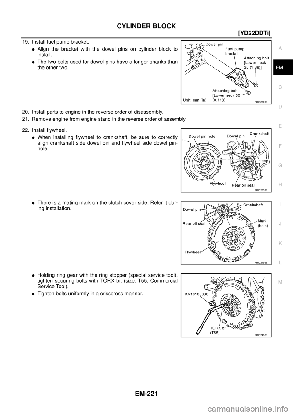
19. Install fuel pump bracket.
�Align the bracket with the dowel pins on cylinder block to
install.
�The two bolts used for dowel pins have a longer shanks than
the other two.
20. Install parts to engine in the reverse order of disassembly.
21. Remove engine from engine stand in the reverse order of assembly.
22. Install flywheel.
�When installing flywheel to crankshaft, be sure to correctly
align crankshaft side dowel pin and flywheel side dowel pin-
hole.
�There is a mating mark on the clutch cover side, Refer it dur-
ing installation.
�Holding ring gear with the ring stopper (special service tool),
tighten securing bolts with TORX bit (size: T55, Commercial
Service Tool).
�Tighten bolts uniformly in a crisscross manner.
PBIC2329E
PBIC2538E
PBIC2495E
PBIC2406E
Page 296 of 4179
![NISSAN X-TRAIL 2003 Service Repair Manual EM-244
[YD22DDTi]
SERVICE DATA AND SPECIFICATIONS (SDS)
AVAILABLE MAIN BEARING
Main bearing
Unit: mm (in)
Under size
Unit: mm (in)
AVAILABLE CONNECTING ROD BEARING
Connecting Rod Bearing
Unit: mm (](/manual-img/5/57404/w960_57404-295.png "NISSAN X-TRAIL 2003 Service Repair Manual EM-244
[YD22DDTi]
SERVICE DATA AND SPECIFICATIONS (SDS)
AVAILABLE MAIN BEARING
Main bearing
Unit: mm (in)
Under size
Unit: mm (in)
AVAILABLE CONNECTING ROD BEARING
Connecting Rod Bearing
Unit: mm (")
EM-244
[YD22DDTi]
SERVICE DATA AND SPECIFICATIONS (SDS)
AVAILABLE MAIN BEARING
Main bearing
Unit: mm (in)
Under size
Unit: mm (in)
AVAILABLE CONNECTING ROD BEARING
Connecting Rod Bearing
Unit: mm (in)
Under size
Unit: mm (in)
MISCELLANEOUS COMPONENTS
Flywheel
Unit: mm (in)
*: Total indicator reading Grade number Thickness “T” Width “W” Identification color
STD 0 1.816 - 1.820 (0.0715 - 0.0717)
19.9 - 20.1 (0.783 - 0.791)Black
STD 1 1.820 - 1.824 (0.0717 - 0.0718) Brown
STD 2 1.824 - 1.828 (0.0718 - 0.0720) Green
STD 3 1.828 - 1.832 (0.0720 - 0.0721) Yellow
STD 4 1.832 - 1.836 (0.0721 - 0.0723) Blue
SEM255G
Size Thickness Main journal diameter “Dm”
0.25 (0.0098) 1.949 - 1.953 (0.0767 - 0.0769)Grind so that bearing clearance is the
specified value.
Grade number Thickness “T” Width “W” Identification color (mark)
STD 0 1.492 - 1.496 (0.0587 - 0.0589)
22.9 - 23.1
(0.902 - 0.909)Black
STD 1 1.496 - 1.500 (0.0589 - 0.0591) Brown
STD 2 1.500 - 1.504 (0.0591 - 0.0592) Green
Size Thickness Crank pin journal diameter “Dp”
0.08 (0.0031) 1.536 - 1.540 (0.0605 - 0.0606)
Grind so that bearing clearance is the
specified value. 0.12 (0.0047) 1.556 - 1.560 (0.0613 - 0.0614)
0.25 (0.0098) 1.621 - 1.625 (0.0638 - 0.0640)
Flywheel deflection [TIR]* Standard 0.45 (0.0177) or less
Page 338 of 4179
CO-6
[QR]
OVERHEATING CAUSE ANALYSIS
Except cool-
ing system
parts mal-
function— Overload on engineAbusive drivingHigh engine rpm under no
load
Driving in low gear for
extended time
Driving at extremely high
speed
Power train system mal-
function
— Installed improper size
wheels and tires
Dragging brakes
Improper ignition timing
Blocked or restricted air
flowBlocked bumper —
— Blocked radiator grilleInstalled car brassiere
Mud contamination or
paper clogging
Blocked radiator —
Blocked condenser
Blocked air flow
Installed large fog lamp Symptom Check items

Wheels & Tires EAS000GG
PAIA0008E
PAIA0009E
PAIA0010")
![NISSAN X-TRAIL 2003 Service Repair Manual PREPARATION
EM-9
[QR]
C
D
E
F
G
H
I
J
K
L
MA
EM
Commercial Service ToolsEBS00L7O
Tool nameDescription
Spark plug wrench Removing and installing spark plug
Pulley holderCrankshaft pulley removing and](/manual-img/5/57404/w960_57404-60.png "NISSAN X-TRAIL 2003 Service Repair Manual PREPARATION
EM-9
[QR]
C
D
E
F
G
H
I
J
K
L
MA
EM
Commercial Service ToolsEBS00L7O
Tool nameDescription
Spark plug wrench Removing and installing spark plug
Pulley holderCrankshaft pulley removing and")
![NISSAN X-TRAIL 2003 Service Repair Manual EM-128
[YD22DDTi]
PREPARATION
To r x s o c k e tRemoving and installing flywheel
Size: T55
Cylinder head bolt wrench Loosening and tightening cylinder head bolt,
and used with angle wrench [SST:](/manual-img/5/57404/w960_57404-179.png "NISSAN X-TRAIL 2003 Service Repair Manual EM-128
[YD22DDTi]
PREPARATION
To r x s o c k e tRemoving and installing flywheel
Size: T55
Cylinder head bolt wrench Loosening and tightening cylinder head bolt,
and used with angle wrench [SST:")
![NISSAN X-TRAIL 2003 Service Repair Manual CO-6
[QR]
OVERHEATING CAUSE ANALYSIS
Except cool-
ing system
parts mal-
function— Overload on engineAbusive drivingHigh engine rpm under no
load
Driving in low gear for
extended time
Driving at](/manual-img/5/57404/w960_57404-337.png "NISSAN X-TRAIL 2003 Service Repair Manual CO-6
[QR]
OVERHEATING CAUSE ANALYSIS
Except cool-
ing system
parts mal-
function— Overload on engineAbusive drivingHigh engine rpm under no
load
Driving in low gear for
extended time
Driving at")