Page 2530 of 3066
MA-38
CHASSIS AND BODY MAINTENANCE
2. Check oil level.
Balancing WheelsELS000BH
Adjust wheel balance using the road wheel center.
RotationELS000BI
lAfter rotating the tires, adjust the tire pressure.
lRetighten the wheel nuts when the vehicle has been driven for
1,000 km (600 miles) (also in cases of a flat tire, etc.).
CAUTION:
When installing wheels, tighten them diagonally by dividing
the work two to three times in order to prevent the wheels
from developing any distortion.
Checking Brake Fluid Level and LeaksELS000BJ
lIf fluid level is extremely low, check brake system for leaks.Oil grad and Viscosity:
Refer toMA-17, "
Fluids and Lubricants"
Capacity:
0.55 (1 lmp pt)
Drain plug:
:30–39N·m(3–4kg-m,22–28ft-lb)
SMA012C
SMA257A
Wheel balance (Maximum allowable unbalance):
Refer toWT-4, "
Balancing Wheels (Bonding Weight Type)".
Tightening torque of wheel nut:
98 - 117N·m (10 - 12 kg·m, 73 - 86 ft·lb)
SMA829C
SFIA0066J
Page 2531 of 3066
CHASSIS AND BODY MAINTENANCE
MA-39
C
D
E
F
G
H
I
J
K
MA
B
MA
Checking Brake Lines and CablesELS000BK
lCheck brake fluid lines and parking brake cables for improper
attachment, leaks, chafing, abrasions, deterioration, etc.
Changing Brake FluidELS000BL
1. Drain brake fluid from each air bleeder valve.
2. Refill until new brake fluid comes out from each air bleeder
valve.
Use same procedure as in bleeding hydraulic system to refill
brake fluid.
Refer toBR-9, "
Changing Brake Fluid".
lRefill with recommended Genuine Brake Fluid or equivalent
“DOT 3” or “DO4”.
Refer toMA-17, "
RECOMMENDED FLUIDS AND LUBRI-
CANTS".
lNever reuse drained brake fluid.
lBe careful not to splash brake fluid on painted areas.
Checking Disc BrakeELS000BM
ROTOR
Check condition, wear, and damage.
CALIPER
lCheck for leakage.
SBR389C
SBR419C
AppliedFront
Brake modelAD31VD
Standard thickness 28.0 mm (1.102 in)
Maximum runout0.04 mm (0.0016 in)
Minimum thickness (Wear limit) 26.0 mm (1.024 in)
SMA922A
Page 2532 of 3066
MA-40
CHASSIS AND BODY MAINTENANCE
PA D
lCheck for wear or damage.
Checking Drum BrakeELS000BN
WHEEL CYLINDER
Check for leakage.
DRUM
Check condition and inner surface.
LINING
Check wear or damage.
Checking Steering Gear and LinkageELS000BO
STEERING GEAR
lCheck gear housing and boots for looseness, damage and
grease leakage.
lCheck connection with steering column for looseness.
STEERING LINKAGE
Check ball joint, dust cover and other component parts for looseness, wear, damage and grease leakage.
Brake model AD31VD
Standard thickness 11.0 mm (0.433 in)
Minimum thickness (Wear Limit) 2.0 mm (0.079 in)
BRA0010D
Standard inner diameter 172 mm (6.77 in)
Drum repair limit (Inner diameter) 173 mm (6.81 in)
SMA848B
Standard thickness 3.5 mm (0.138 in)
Lining Wear Limit (Minimum thickness) 1.5 mm (0.059 in)
SMA849B
SLIA0014E
Page 2533 of 3066

CHASSIS AND BODY MAINTENANCE
MA-41
C
D
E
F
G
H
I
J
K
MA
B
MA
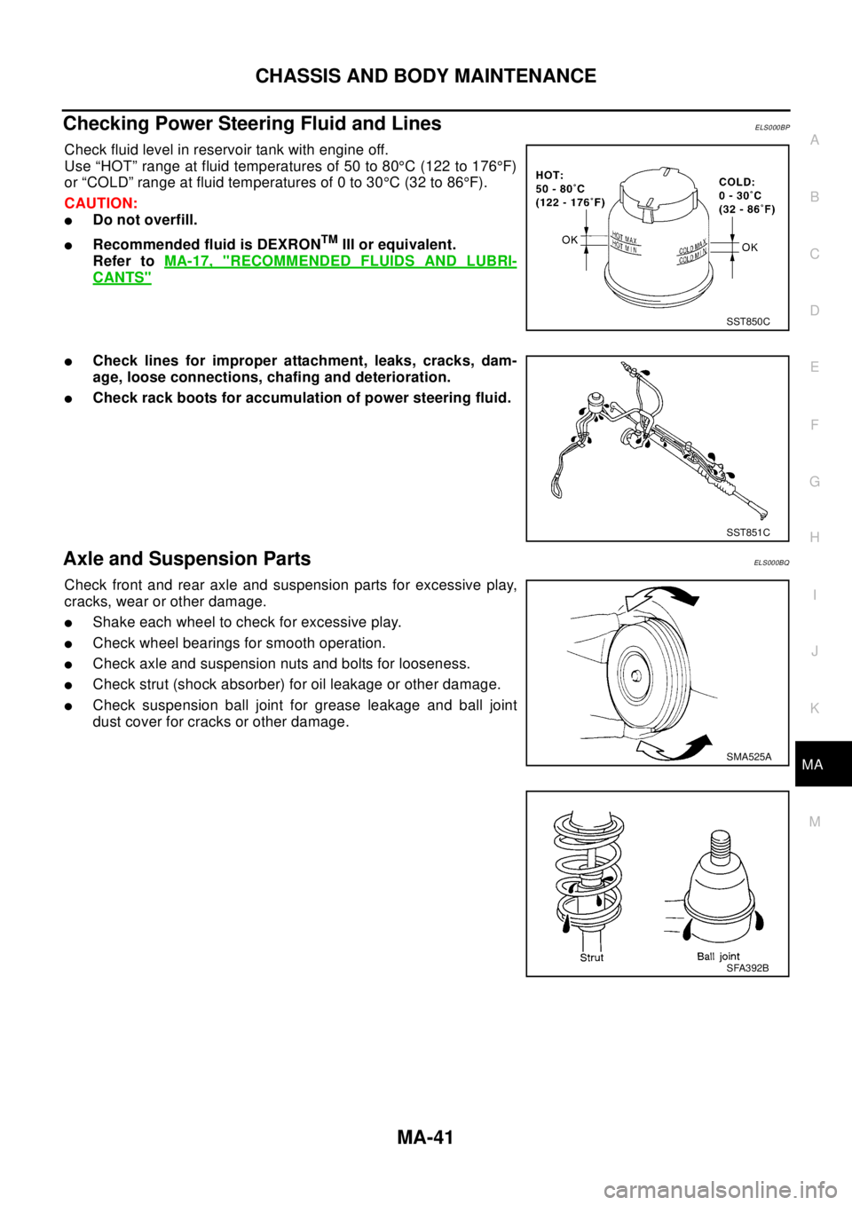
Checking Power Steering Fluid and LinesELS000BP
Check fluid level in reservoir tank with engine off.
Use “HOT” range at fluid temperatures of 50 to 80°C (122 to 176°F)
or “COLD” range at fluid temperatures of 0 to 30°C(32to86°F).
CAUTION:
lDo not overfill.
lRecommended fluid is DEXRONTMIII or equivalent.
Refer toMA-17, "
RECOMMENDED FLUIDS AND LUBRI-
CANTS"
lCheck lines for improper attachment, leaks, cracks, dam-
age, loose connections, chafing and deterioration.
lCheck rack boots for accumulation of power steering fluid.
Axle and Suspension PartsELS000BQ
Check front and rear axle and suspension parts for excessive play,
cracks, wear or other damage.
lShake each wheel to check for excessive play.
lCheck wheel bearings for smooth operation.
lCheck axle and suspension nuts and bolts for looseness.
lCheck strut (shock absorber) for oil leakage or other damage.
lCheck suspension ball joint for grease leakage and ball joint
dust cover for cracks or other damage.
SST850C
SST851C
SMA525A
SFA392B
Page 2534 of 3066
MA-42
CHASSIS AND BODY MAINTENANCE
Drive Shaft
ELS000CL
lCheck boot and drive shaft for cracks, wear, damage and
grease leakage.
Lubricating Locks, Hinges and Hood LatchesELS000BR
Checking Seat Belts, Buckles, Retractors, Anchors and AdjustersELS000BS
Checking Body CorrosionELS000C0
Visually check body panels for collision damage (scratches, chipping, rubbing, etc.) or damage to the anti-cor-
rosion materials. In particular, check the following locations.
HEMMED PANELS
Hood front end, door lower end, trunk lid rear end, etc.
PANEL JOINT
Side sill of rear fender and center pillar, rear wheel housing of rear fender, around strut tower in engine com-
partment, etc.
PANEL EDGE
Trunk lid opening, sunroof opening, fender wheel-arch flange, fuel filler lid flange, around holes in panel, etc.
PA R T S C O N TA C T
Waist moulding, windshield moulding, bumper, etc.
SFA108A
Front door Refer toBL-8, "DOOR".
Back door Refer toBL-60, "
BACK DOOR".
Page 2535 of 3066
CHASSIS AND BODY MAINTENANCE
MA-43
C
D
E
F
G
H
I
J
K
MA
B
MA
PROTECTORS
Damage or condition of mudguard, fender protector, chipping protector, etc.
ANTI-CORROSION MATERIALS
Damage or separation of anti-corrosion materials under the body.
DRAIN HOLES
Condition of drain holes at door and side sill. When repairing corroded areas, refer to the Corrosion Repair
Manual.
Page 2638 of 3066

MTC-2
PRECAUTIONS
PRECAUTIONS
PFP:00001
Precautions for Supplemental Restraint System (SRS) “AIR BAG” and “SEAT
BELT PRE-TENSIONER”
EJS000W1
The Supplemental Restraint System such as “AIR BAG” and “SEAT BELT PRE-TENSIONER”, used along
with a front seat belt, helps to reduce the risk or severity of injury to the driver and front passenger for certain
types of collision. Information necessary to service the system safely is included in the SRS and SB section of
this Service Manual.
WAR NIN G:
lTo avoid rendering the SRS inoperative, which could increase the risk of personal injury or death
in the event of a collision which would result in air bag inflation, all maintenance must be per-
formed by an authorized NISSAN/INFINITI dealer.
lImproper maintenance, including incorrect removal and installation of the SRS, can lead to per-
sonal injury caused by unintentional activation of the system. For removal of Spiral Cable and Air
Bag Module, see the SRS section.
lDo not use electrical test equipment on any circuit related to the SRS unless instructed to in this
Service Manual. SRS wiring harnesses can be identified by yellow harness connectors.
Wiring Diagrams and Trouble DiagnosisEJS000WA
When you read wiring diagrams, refer to the followings:
lGI-14, "How to Read Wiring Diagrams"in GI section.
lPG-3, "Wiring Diagram—POWER—"in EL section.
When you perform trouble diagnosis, refer to the followings:
lGI-10, "How to Follow Trouble Diagnoses"in GI section.
lGI-24, "How to Perform Efficient Diagnosis for an Electrical Incident"in GI section.
Page 2868 of 3066

SB-2
PRECAUTIONS
PRECAUTIONS
PFP:00001
Supplemental Restraint System (SRS) “AIR BAG” and “SEAT BELT PRE-TEN-
SIONER”
EHS000BD
The Supplemental Restraint System such as “AIR BAG” and “SEAT BELT PRE-TENSIONER” used along with
a front seat belt, helps to reduce the risk or severity of injury to the driver and front passenger for certain types
of collision.
WAR NIN G:
lTo avoid rendering the SRS inoperative, which could increase the risk of personal injury or death
in the event of a collision which would result in air bag inflation, all maintenance should be per-
formed by an authorized NISSAN /INFINITI dealer.
lImproper maintenance, including incorrect removal and installation of the SRS, can lead to per-
sonal injury caused by unintentional activation of the system.
lDo not use electrical test equipment on any circuit related to the SRS unless instructed to in this
Service Manual. SRS wiring harnesses can be identified by yellow harness connector.
Precaution for Seat Belt ServiceEHS000BE
CAUTION:
lBefore removing the seat belt pre-tensioner assembly, turn the ignition switch off, disconnect the
battery ground cable and wait at least 3 minutes.
lDo not use electrical test equipment for seat belt pre-tensioner connector.
lAfter replacing or reinstalling seat belt pre-tensioner assembly, or reconnecting seat belt pre-ten-
sioner connector, check the system function. Refer toSRS-15, "
SRS Operation Check".
lDo not use disassemble buckle or seat belt assembly.
lReplace anchor bolts if they are deformed or worn out.
lNever oil tongue and buckle.
lIf any component of seat belt assembly is questionable, do not repair. Replace the whole seat belt
assembly.
lIf webbing is cut, frayed, or damaged, replace seat belt assembly.
lWhen replacing seat belt assembly, use a genuine seat belt assembly.
AFTER A COLLISION
WAR NIN G:
Inspect all seat belt assemblies including retractors and attaching hardware after any collision.
NISSAN recommends that all seat belt assemblies in use during a collision be replaced unless the col-
lision was minor and the belts show no damage and continue to operate properly. Failure to do so
could result in serious personal injury in an accident. Seat belt assemblies not in use during a colli-
sion should also be replaced if either damage or improper operation is noted. Seat belt pre-tensioner
should be replaced even if the seat belts are not in use during a frontal collision in which the air bags
are deployed.
Replace any seat belt assembly (including anchor bolts) if:
lThe seat belt was in use at the time of a collision (except for minor collisions and the belts, retractors and
buckles show no damage and continue to operate properly).
lThe seat belt was damaged in an accident. (i.e. torn webbing, bent retractor or guide, etc.)
lThe seat belt attaching point was damaged in an accident. Inspect the seat belt attaching area for damage
or distortion and repair as necessary before installing a new seat belt assembly.
lAnchor bolts are deformed or worn out.
lThe seat belt pre-tensioner should be replaced even if the seat belts are not in use during the collision in
which the air bags are deployed.