Page 3028 of 3066
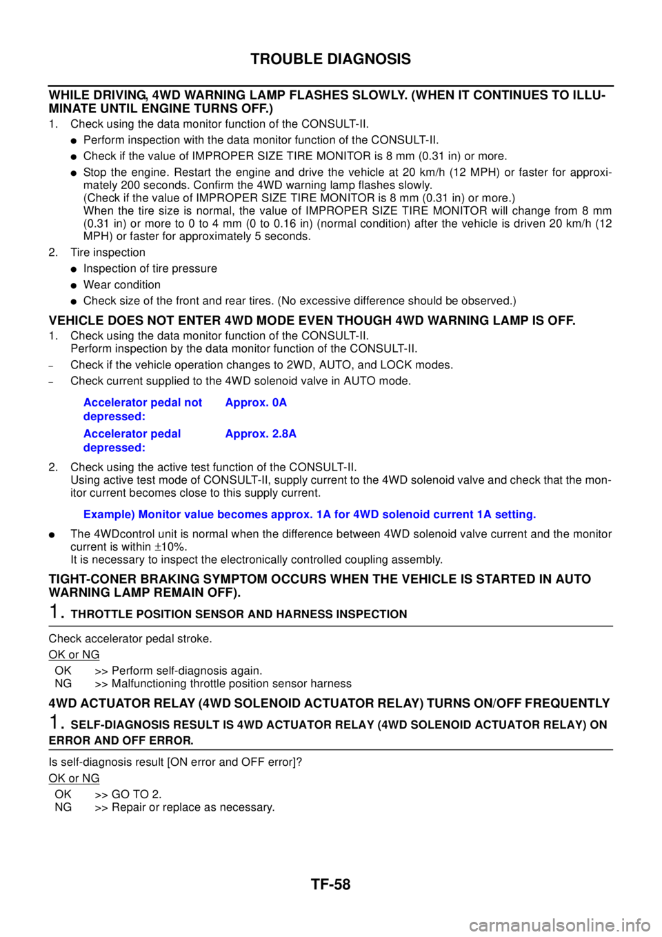
TF-58
TROUBLE DIAGNOSIS
WHILE DRIVING, 4WD WARNING LAMP FLASHES SLOWLY. (WHEN IT CONTINUES TO ILLU-
MINATE UNTIL ENGINE TURNS OFF.)
1. Check using the data monitor function of the CONSULT-II.
lPerform inspection with the data monitor function of the CONSULT-II.
lCheck if the value of IMPROPER SIZE TIRE MONITOR is 8 mm (0.31 in) or more.
lStop the engine. Restart the engine and drive the vehicle at 20 km/h (12 MPH) or faster for approxi-
mately 200 seconds. Confirm the 4WD warning lamp flashes slowly.
(Check if the value of IMPROPER SIZE TIRE MONITOR is 8 mm (0.31 in) or more.)
When the tire size is normal, the value of IMPROPER SIZE TIRE MONITOR will change from 8 mm
(0.31 in) or more to 0 to 4 mm (0 to 0.16 in) (normal condition) after the vehicle is driven 20 km/h (12
MPH) or faster for approximately 5 seconds.
2. Tire inspection
lInspection of tire pressure
lWear condition
lCheck size of the front and rear tires. (No excessive difference should be observed.)
VEHICLE DOES NOT ENTER 4WD MODE EVEN THOUGH 4WD WARNING LAMP IS OFF.
1. Check using the data monitor function of the CONSULT-II.
Perform inspection by the data monitor function of the CONSULT-II.
–Check if the vehicle operation changes to 2WD, AUTO, and LOCK modes.
–Check current supplied to the 4WD solenoid valve in AUTO mode.
2. Check using the active test function of the CONSULT-II.
Using active test mode of CONSULT-II, supply current to the 4WD solenoid valve and check that the mon-
itor current becomes close to this supply current.
lThe 4WDcontrol unit is normal when the difference between 4WD solenoid valve current and the monitor
current is within±10%.
It is necessary to inspect the electronically controlled coupling assembly.
TIGHT-CONER BRAKING SYMPTOM OCCURS WHEN THE VEHICLE IS STARTED IN AUTO
WARNING LAMP REMAIN OFF).
1.THROTTLE POSITION SENSOR AND HARNESS INSPECTION
Check accelerator pedal stroke.
OK or NG
OK >> Perform self-diagnosis again.
NG >> Malfunctioning throttle position sensor harness
4WD ACTUATOR RELAY (4WD SOLENOID ACTUATOR RELAY) TURNS ON/OFF FREQUENTLY
1.SELF-DIAGNOSIS RESULT IS 4WD ACTUATOR RELAY (4WD SOLENOID ACTUATOR RELAY) ON
ERROR AND OFF ERROR.
Is self-diagnosis result [ON error and OFF error]?
OK or NG
OK >> GO TO 2.
NG >> Repair or replace as necessary.Accelerator pedal not
depressed:Approx. 0A
Accelerator pedal
depressed:Approx. 2.8A
Example) Monitor value becomes approx. 1A for 4WD solenoid current 1A setting.
Page 3042 of 3066

WW-4
FRONT WIPER AND WASHER SYSTEM
FRONT WIPER AND WASHER SYSTEM
PFP:28810
System DescriptionEKS0032N
WIPER OPERATION
The wiper switch is controlled by a lever built into the combination switch.
There are three wiper switch positions:
lLO speed
lHI speed
lINT (Intermittent)
With the ignition switch in the ON or START position, power is supplied
lthrough 20A fuse [No. 6, located in the fuse block (J/B)]
lto front wiper motor terminal 4.
LOW AND HIGH SPEED WIPER OPERATION
Ground is supplied to wiper and washer switch terminal 17 through body grounds E24 and E50.
When the wiper switch is placed in the LO position, ground is supplied
lthrough terminal 14 of the front wiper and washer switch
lto front wiper motor terminal 3.
With power and ground supplied, the wiper motor operates at low speed.
When the wiper switch is placed in the HI position, ground is supplied
lthrough terminal 16 of the front wiper and washer switch
lto wiper motor terminal 1.
With power and ground supplied, the wiper motor operates at high speed.
AUTO STOP OPERATION
With wiper switch turned OFF, wiper motor will continue to operate until wiper arms reach windshield base.
When wiper arms are not located at base of windshield with wiper switch OFF, ground is provided
lfrom terminal 14 of the front wiper and washer switch
lto front wiper motor terminal 3, in order to continue wiper motor operation at low speed.
Ground is also supplied
lthrough terminal 13 of the front wiper and washer switch
lto front wiper motor terminal 2
lthrough terminal 6 of the front wiper motor, and
lthrough body grounds E24 and E50.
When wiper arms reach base of windshield, front wiper motor terminals 4 and 2 are connected instead of ter-
minals 6 and 2. Wiper motor will then stop wiper arms at the STOP position.
INTERMITTENT OPERATION
The front wiper motor operates the wiper arms one time at low speed at a set interval of approximately 1 to 13
seconds. This feature is controlled by the wiper amplifier (INT SW) combined with front wiper and washer
switch.
When the wiper switch is placed in the INT position, ground is supplied to wiper amplifier.
The desired interval time is input to wiper amplifier (INT VR) from wiper volume switch combined with front
wiper and washer switch.
Then intermittent ground is supplied
lthrough wiper amplifier (OUTPUT) and
lthrough terminal 14 of front wiper and washer switch
lto front wiper motor terminal 3
The wiper motor operates at low speed at the desired interval.
WASHER OPERATION
With the ignition switch in the ON or START position, power is supplied
lthrough 20A fuse [No. 6, located in the fuse block (J/B)]
lto washer motor terminal 1.
Page 3057 of 3066
HEADLAMP WASHER
WW-19
C
D
E
F
G
H
I
J
L
MA
B
WW
HEADLAMP WASHERPFP:28620
System DescriptionEKS0036H
The headlamp washer is controlled by the headlamp washer timer. Power is supplied at all times. With power
and ground supplied, the headlamp washer motor operates.
lthrough 30A fusible link (letter E, located in fuse and fusible link box)
lto headlamp washer motor terminal 1, and
lthrough10Afuse(No.31,locatedinfuseandfusiblelinkbox)
lto lighting switch terminal 11.
lthrough 10A fuse [No. 11, located in fuse block (J/B)]
lto headlamp washer timer terminal 4.
Ground is supplied to headlamp washer timer terminal 5 through body grounds E24 and E50. When headlamp
washer switch is pushed during lighting switch is in 1st or 2ND position, ground is supplied
lto headlamp washer timer terminal 6
lthrough headlamp washer switch and body grounds M27 and M70, and
lto headlamp washer motor terminal 2
lthrough headlamp washer timer terminal 3.
With ignition switch in the ON or START position, power is supplied