Page 2737 of 3066

HARNESS
PG-61
C
D
E
F
G
H
I
J
L
MA
B
PG
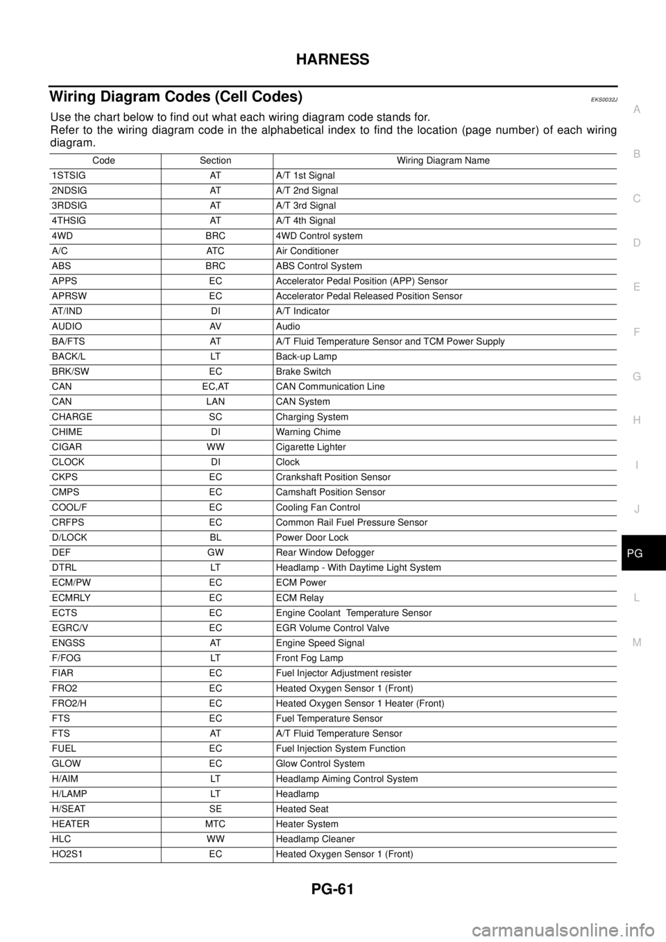
Wiring Diagram Codes (Cell Codes)EKS0032J
Use the chart below to find out what each wiring diagram code stands for.
Refer to the wiring diagram code in the alphabetical index to find the location (page number) of each wiring
diagram.
Code Section Wiring Diagram Name
1STSIG AT A/T 1st Signal
2NDSIG AT A/T 2nd Signal
3RDSIG AT A/T 3rd Signal
4THSIG AT A/T 4th Signal
4WD BRC 4WD Control system
A/C ATC Air Conditioner
ABS BRC ABS Control System
APPS EC Accelerator Pedal Position (APP) Sensor
APRSW EC Accelerator Pedal Released Position Sensor
AT/IND DI A/T Indicator
AUDIO AV Audio
BA/FTS AT A/T Fluid Temperature Sensor and TCM Power Supply
BACK/L LT Back-up Lamp
BRK/SW EC Brake Switch
CAN EC,AT CAN Communication Line
CAN LAN CAN System
CHARGE SC Charging System
CHIME DI Warning Chime
CIGAR WW Cigarette Lighter
CLOCK DI Clock
CKPS EC Crankshaft Position Sensor
CMPS EC Camshaft Position Sensor
COOL/F EC Cooling Fan Control
CRFPS EC Common Rail Fuel Pressure Sensor
D/LOCK BL Power Door Lock
DEF GW Rear Window Defogger
DTRL LT Headlamp - With Daytime Light System
ECM/PW EC ECM Power
ECMRLY EC ECM Relay
ECTS EC Engine Coolant Temperature Sensor
EGRC/V EC EGR Volume Control Valve
ENGSS AT Engine Speed Signal
F/FOG LT Front Fog Lamp
FIAR EC Fuel Injector Adjustment resister
FRO2 EC Heated Oxygen Sensor 1 (Front)
FRO2/H EC Heated Oxygen Sensor 1 Heater (Front)
FTS EC Fuel Temperature Sensor
FTS AT A/T Fluid Temperature Sensor
FUEL EC Fuel Injection System Function
GLOW EC Glow Control System
H/AIM LT Headlamp Aiming Control System
H/LAMP LT Headlamp
H/SEAT SE Heated Seat
HEATER MTC Heater System
HLC WW Headlamp Cleaner
HO2S1 EC Heated Oxygen Sensor 1 (Front)
Page 3039 of 3066

WW-1
WIPER, WASHER & HORN
K ELECTRICAL
CONTENTS
C
D
E
F
G
H
I
J
L
M
SECTION
A
B
WW
WIPER, WASHER & HORN
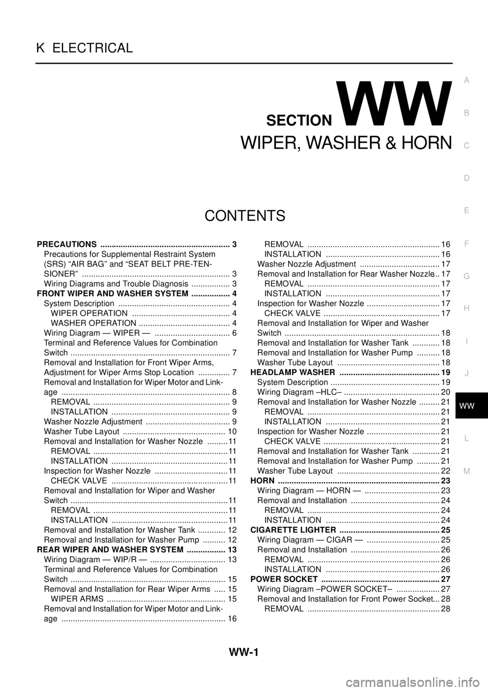
PRECAUTIONS .......................................................... 3
Precautions for Supplemental Restraint System
(SRS) “AIR BAG” and “SEAT BELT PRE-TEN-
SIONER” .................................................................. 3
Wiring Diagrams and Trouble Diagnosis .................. 3
FRONT WIPER AND WASHER SYSTEM .................. 4
System Description .................................................. 4
WIPER OPERATION ............................................ 4
WASHER OPERATION ......................................... 4
Wiring Diagram — WIPER — .................................. 6
Terminal and Reference Values for Combination
Switch ....................................................................... 7
Removal and Installation for Front Wiper Arms,
Adjustment for Wiper Arms Stop Location ............... 7
Removal and Installation for Wiper Motor and Link-
age ........................................................................... 8
REMOVAL ............................................................. 9
INSTALLATION ..................................................... 9
Washer Nozzle Adjustment ...................................... 9
Washer Tube Layout .............................................. 10
Removal and Installation for Washer Nozzle ..........11
REMOVAL ............................................................11
INSTALLATION ....................................................11
Inspection for Washer Nozzle .................................11
CHECK VALVE ....................................................11
Removal and Installation for Wiper and Washer
Switch ......................................................................11
REMOVAL ............................................................11
INSTALLATION ....................................................11
Removal and Installation for Washer Tank ............. 12
Removal and Installation for Washer Pump ........... 12
REAR WIPER AND WASHER SYSTEM .................. 13
Wiring Diagram — WIP/R — .................................. 13
Terminal and Reference Values for Combination
Switch ..................................................................... 15
Removal and Installation for Rear Wiper Arms ...... 15
WIPER ARMS ..................................................... 15
Removal and Installation for Wiper Motor and Link-
age ......................................................................... 16REMOVAL ........................................................... 16
INSTALLATION ................................................... 16
Washer Nozzle Adjustment .................................... 17
Removal and Installation for Rear Washer Nozzle... 17
REMOVAL ........................................................... 17
INSTALLATION ................................................... 17
Inspection for Washer Nozzle ................................. 17
CHECK VALVE .................................................... 17
Removal and Installation for Wiper and Washer
Switch ..................................................................... 18
Removal and Installation for Washer Tank ............. 18
Removal and Installation for Washer Pump ........... 18
Washer Tube Layout .............................................. 18
HEADLAMP WASHER ............................................. 19
System Description ................................................. 19
Wiring Diagram –HLC– ........................................... 20
Removal and Installation for Washer Nozzle .......... 21
REMOVAL ........................................................... 21
INSTALLATION ................................................... 21
Inspection for Washer Nozzle ................................. 21
CHECK VALVE .................................................... 21
Removal and Installation for Washer Tank ............. 21
Removal and Installation for Washer Pump ........... 21
Washer Tube Layout .............................................. 22
HORN ........................................................................ 23
Wiring Diagram — HORN — .................................. 23
Removal and Installation ........................................ 24
REMOVAL ........................................................... 24
INSTALLATION ................................................... 24
CIGARETTE LIGHTER ............................................. 25
Wiring Diagram — CIGAR — ................................. 25
Removal and Installation ........................................ 26
REMOVAL ........................................................... 26
INSTALLATION ................................................... 26
POWER SOCKET ..................................................... 27
Wiring Diagram –POWER SOCKET– .................... 27
Removal and Installation for Front Power Socket... 28
REMOVAL ........................................................... 28
Page 3057 of 3066

HEADLAMP WASHER
WW-19
C
D
E
F
G
H
I
J
L
MA
B
WW
HEADLAMP WASHERPFP:28620
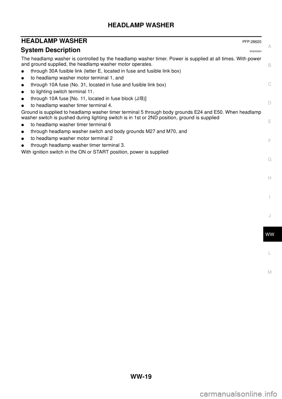
System DescriptionEKS0036H
The headlamp washer is controlled by the headlamp washer timer. Power is supplied at all times. With power
and ground supplied, the headlamp washer motor operates.
lthrough 30A fusible link (letter E, located in fuse and fusible link box)
lto headlamp washer motor terminal 1, and
lthrough10Afuse(No.31,locatedinfuseandfusiblelinkbox)
lto lighting switch terminal 11.
lthrough 10A fuse [No. 11, located in fuse block (J/B)]
lto headlamp washer timer terminal 4.
Ground is supplied to headlamp washer timer terminal 5 through body grounds E24 and E50. When headlamp
washer switch is pushed during lighting switch is in 1st or 2ND position, ground is supplied
lto headlamp washer timer terminal 6
lthrough headlamp washer switch and body grounds M27 and M70, and
lto headlamp washer motor terminal 2
lthrough headlamp washer timer terminal 3.
With ignition switch in the ON or START position, power is supplied
Page 3058 of 3066
WW-20
HEADLAMP WASHER
Wiring Diagram –HLC–
EKS0036I
TKWA0107E
Page 3059 of 3066
HEADLAMP WASHER
WW-21
C
D
E
F
G
H
I
J
L
MA
B
WW
Removal and Installation for Washer NozzleEKS0036J
REMOVAL
1. Remove front bumper, refer toEI-6, "FRONT BUMPER"
2. Remove hose clip and washer nozzle metal clip.
3. Remove washer nozzle from front bumper.
INSTALLATION
Installation is in the reverse order of removal.
Inspection for Washer NozzleEKS0036K
CHECK VALVE
lBlow air in the injection direction, and check that air flows only
one way. Make sure that the reverse direction is not possible.
Removal and Installation for Washer TankEKS0036L
Refer to,WW-12, "Removal and Installation for Washer Tank"
Removal and Installation for Washer PumpEKS0036M
1. Remove front bumper, refer toEI-6, "FRONT BUMPER"
2. Remove washer pump connector and hose.
3. Pull out washer pump in the direction of the arrow in the figure,
and remove the washer pump from the washer tank.
CAUTION:
When installing washer pump, there should be no packing twist,
etc.
PKIA0490E
PKIA0491E
PKIA0494E
Page 3060 of 3066
WW-22
HEADLAMP WASHER
Washer Tube Layout
EKS0036N
PKIA0539E