2003 NISSAN X-TRAIL checking oil
[x] Cancel search: checking oilPage 2765 of 3066
POWER STEERING FLUID
PS-5
C
D
E
F
H
I
J
K
L
MA
B
PS
POWER STEERING FLUIDPFP:KLF20
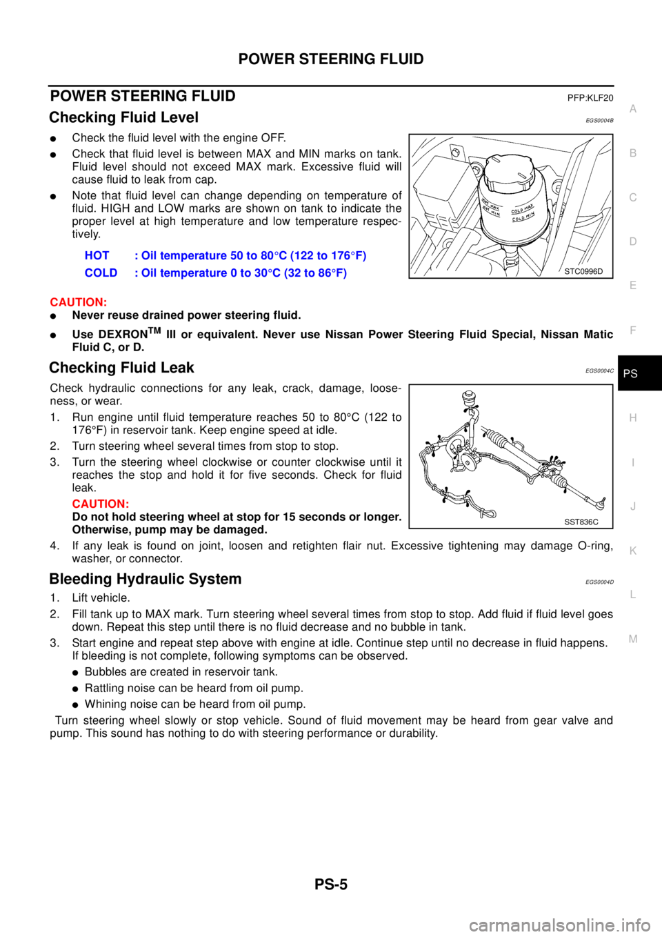
Checking Fluid LevelEGS0004B
lCheck the fluid level with the engine OFF.
lCheck that fluid level is between MAX and MIN marks on tank.
Fluid level should not exceed MAX mark. Excessive fluid will
cause fluid to leak from cap.
lNote that fluid level can change depending on temperature of
fluid. HIGH and LOW marks are shown on tank to indicate the
proper level at high temperature and low temperature respec-
tively.
CAUTION:
lNever reuse drained power steering fluid.
lUse DEXRONTMIII or equivalent. Never use Nissan Power Steering Fluid Special, Nissan Matic
Fluid C, or D.
Checking Fluid LeakEGS0004C
Check hydraulic connections for any leak, crack, damage, loose-
ness, or wear.
1. Run engine until fluid temperature reaches 50 to 80°C (122 to
176°F) in reservoir tank. Keep engine speed at idle.
2. Turn steering wheel several times from stop to stop.
3. Turn the steering wheel clockwise or counter clockwise until it
reaches the stop and hold it for five seconds. Check for fluid
leak.
CAUTION:
Do not hold steering wheel at stop for 15 seconds or longer.
Otherwise, pump may be damaged.
4. If any leak is found on joint, loosen and retighten flair nut. Excessive tightening may damage O-ring,
washer, or connector.
Bleeding Hydraulic SystemEGS0004D
1. Lift vehicle.
2. Fill tank up to MAX mark. Turn steering wheel several times from stop to stop. Add fluid if fluid level goes
down. Repeat this step until there is no fluid decrease and no bubble in tank.
3. Start engine and repeat step above with engine at idle. Continue step until no decrease in fluid happens.
If bleeding is not complete, following symptoms can be observed.
lBubbles are created in reservoir tank.
lRattling noise can be heard from oil pump.
lWhiningnoisecanbeheardfromoilpump.
Turn steering wheel slowly or stop vehicle. Sound of fluid movement may be heard from gear valve and
pump. This sound has nothing to do with steering performance or durability.HOT : Oil temperature 50 to 80°C (122 to 176°F)
COLD : Oil temperature 0 to 30°C(32to86°F)
STC0996D
SST836C
Page 2826 of 3066
RFD-4
PREPARATION
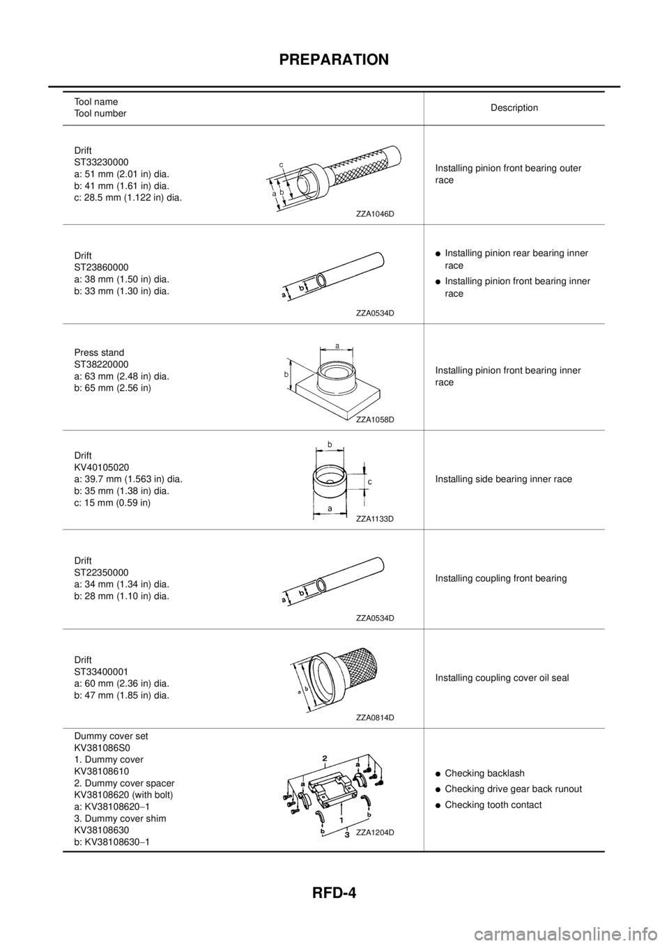
Drift
ST33230000
a: 51 mm (2.01 in) dia.
b: 41 mm (1.61 in) dia.
c: 28.5 mm (1.122 in) dia.Installing pinion front bearing outer
race
Drift
ST23860000
a: 38 mm (1.50 in) dia.
b: 33 mm (1.30 in) dia.
lInstalling pinion rear bearing inner
race
lInstalling pinion front bearing inner
race
Press stand
ST38220000
a: 63 mm (2.48 in) dia.
b: 65 mm (2.56 in)Installing pinion front bearing inner
race
Drift
KV40105020
a: 39.7 mm (1.563 in) dia.
b: 35 mm (1.38 in) dia.
c: 15 mm (0.59 in)Installing side bearing inner race
Drift
ST22350000
a: 34 mm (1.34 in) dia.
b: 28 mm (1.10 in) dia.Installing coupling front bearing
Drift
ST33400001
a: 60 mm (2.36 in) dia.
b: 47 mm (1.85 in) dia.Installing coupling cover oil seal
Dummy cover set
KV381086S0
1. Dummy cover
KV38108610
2. Dummy cover spacer
KV38108620 (with bolt)
a: KV38108620-1
3. Dummy cover shim
KV38108630
b: KV38108630-1
lChecking backlash
lChecking drive gear back runout
lChecking tooth contact Tool name
Tool numberDescription
ZZA1046D
ZZA0534D
ZZA1058D
ZZA1133D
ZZA0534D
ZZA0814D
ZZA1204D
Page 2844 of 3066
RFD-22
REAR FINAL DRIVE ASSEMBLY
ASSEMBLY
Assembly of drive pinion gear assembly
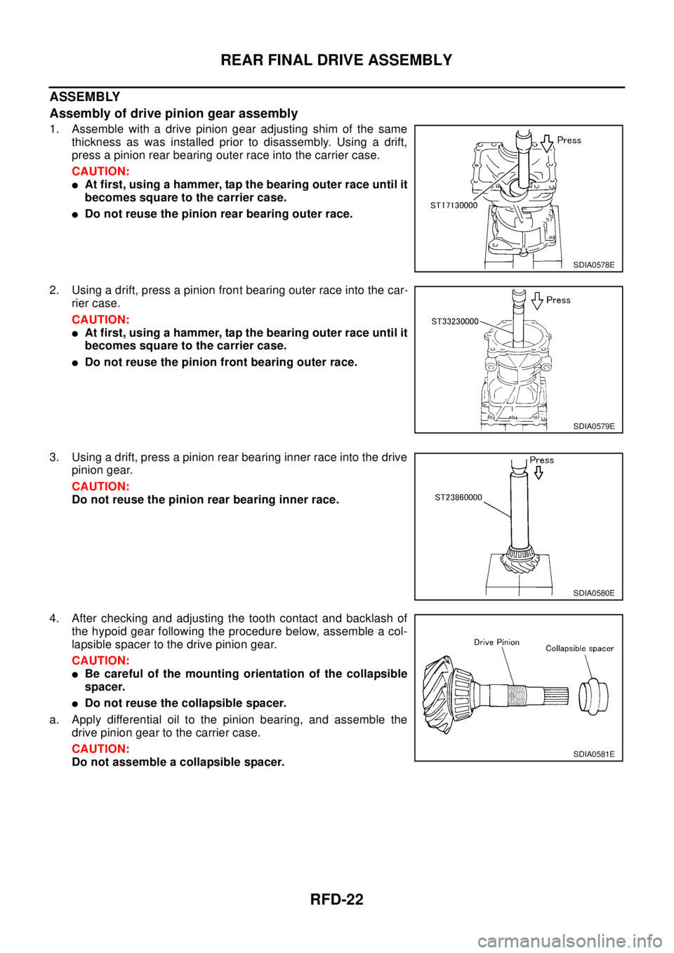
1. Assemble with a drive pinion gear adjusting shim of the same
thickness as was installed prior to disassembly. Using a drift,
press a pinion rear bearing outer race into the carrier case.
CAUTION:
lAt first, using a hammer, tap the bearing outer race until it
becomes square to the carrier case.
lDo not reuse the pinion rear bearing outer race.
2. Using a drift, press a pinion front bearing outer race into the car-
rier case.
CAUTION:
lAt first, using a hammer, tap the bearing outer race until it
becomes square to the carrier case.
lDo not reuse the pinion front bearing outer race.
3. Using a drift, press a pinion rear bearing inner race into the drive
pinion gear.
CAUTION:
Do not reuse the pinion rear bearing inner race.
4. After checking and adjusting the tooth contact and backlash of
the hypoid gear following the procedure below, assemble a col-
lapsible spacer to the drive pinion gear.
CAUTION:
lBe careful of the mounting orientation of the collapsible
spacer.
lDo not reuse the collapsible spacer.
a. Apply differential oil to the pinion bearing, and assemble the
drive pinion gear to the carrier case.
CAUTION:
Do not assemble a collapsible spacer.
SDIA0578E
SDIA0579E
SDIA0580E
SDIA0581E
Page 2886 of 3066
SC-14
CHARGING SYSTEM
Trouble Diagnoses
EKS00319
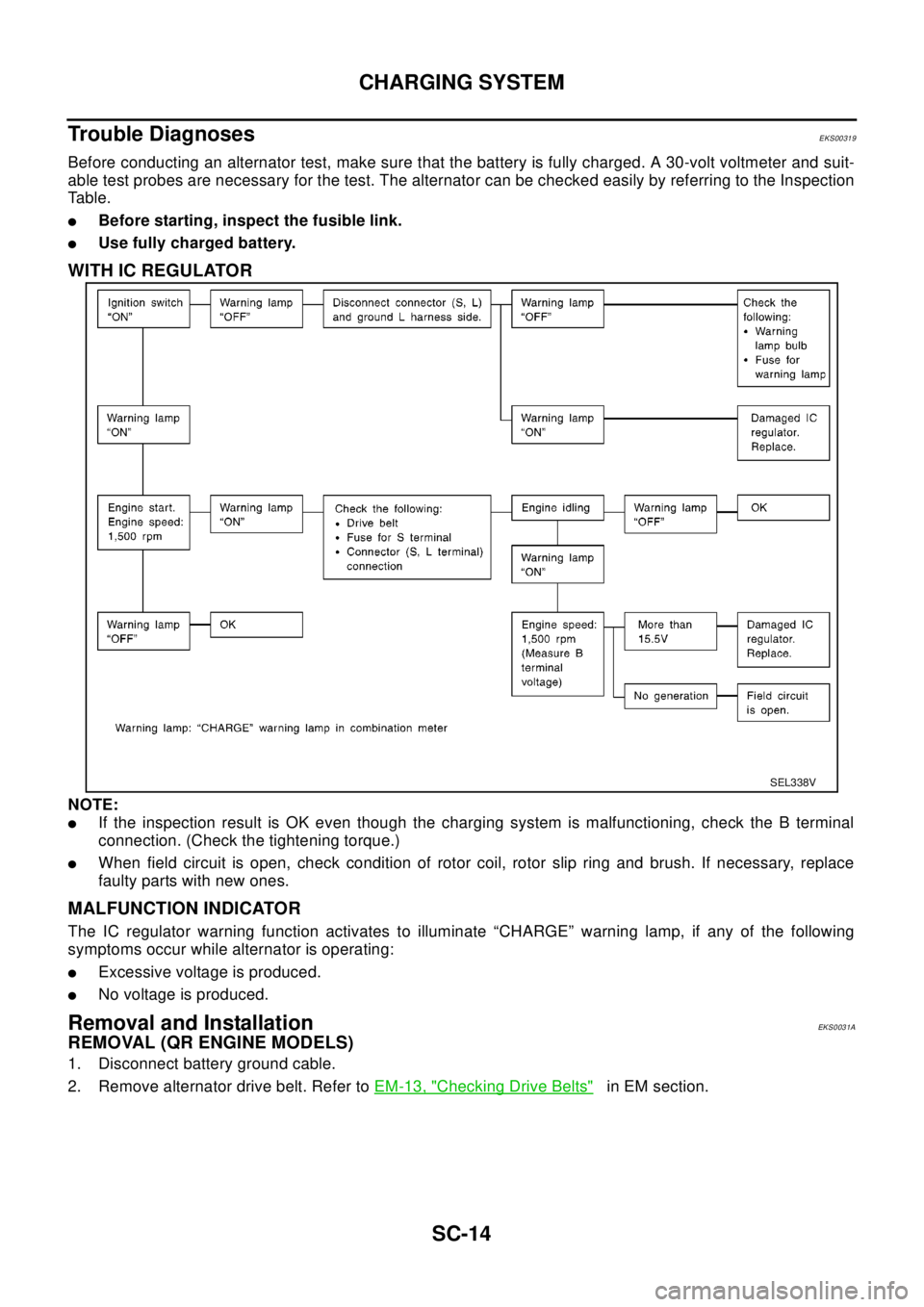
Before conducting an alternator test, make sure that the battery is fully charged. A 30-volt voltmeter and suit-
able test probes are necessary for the test. The alternator can be checked easily by referring to the Inspection
Table.
lBefore starting, inspect the fusible link.
lUse fully charged battery.
WITH IC REGULATOR
NOTE:
lIf the inspection result is OK even though the charging system is malfunctioning, check the B terminal
connection. (Check the tightening torque.)
lWhen field circuit is open, check condition of rotor coil, rotor slip ring and brush. If necessary, replace
faulty parts with new ones.
MALFUNCTION INDICATOR
The IC regulator warning function activates to illuminate “CHARGE” warning lamp, if any of the following
symptoms occur while alternator is operating:
lExcessive voltage is produced.
lNo voltage is produced.
Removal and InstallationEKS0031A
REMOVAL (QR ENGINE MODELS)
1. Disconnect battery ground cable.
2. Remove alternator drive belt. Refer toEM-13, "
Checking Drive Belts"in EM section.
SEL338V
Page 2977 of 3066

NOISE, VIBRATION, AND HARSHNESS (NVH) TROUBLESHOOTING
TF-7
C
E
F
G
H
I
J
K
L
MA
B
TF
NOISE, VIBRATION, AND HARSHNESS (NVH) TROUBLESHOOTINGPFP:00003
NVH Troubleshooting ChartEDS000I4
Use the chart below to help you find the cause of the problem.The numbers indicate the order of the inspec-
tion. If necessary, repair or replace these parts.
Reference page
Refer to MA section("Checking Transfer Fluid"
("CHASSIS AND BODY MAINTENANCE").
TF-14
TF-14TF-23TF-24
Possible cause and Suspected parts
FLUID (Level low)
FLUID (Wrong)
FLUID (Level too high)
LIQUID GASKET (Damaged)
OIL SEAL (Worn or damaged)
GEAR (Worn or damaged)
BEARING (Worn or damaged)
SymptomNoise 1 2 3 3
Fluidleakage 3122
jumps out of gear 1
Page 2996 of 3066
TF-26
TRANSFER ASSEMBLY
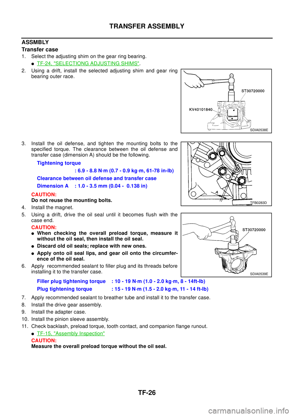
ASSMBLY
Transfer case
1. Select the adjusting shim on the gear ring bearing.
lTF-24, "SELECTIONG ADJUSTING SHIMS".
2. Using a drift, install the selected adjusting shim and gear ring
bearing outer race.
3. Install the oil defense, and tighten the mounting bolts to the
specified torque. The clearance between the oil defense and
transfer case (dimension A) should be the following.
CAUTION:
Do not reuse the mounting bolts.
4. Install the magnet.
5. Using a drift, drive the oil seal until it becomes flush with the
case end.
CAUTION:
lWhen checking the overall preload torque, measure it
without the oil seal, then install the oil seal.
lDiscard old oil seals; replace with new ones.
lApply onto oil seal lips, and gear oil onto the circumfer-
ence of the oil seal.
6. Apply recommended sealant to filler plug and its threads before
installing it to the transfer case.
7. Apply recommended sealant to breather tube and install it to the transfer case.
8. Install the drive gear assembly.
9. Install the adapter case.
10. Install the pinion sleeve assembly.
11. Check backlash, preload torque, tooth contact, and companion flange runout.
lTF-15, "Assembly Inspection"
CAUTION:
Measure the overall preload torque without the oil seal.
SDIA0538E
Tightening torque
: 6.9 - 8.8 N·m (0.7 - 0.9 kg·m, 61-78 in-lb)
Clearance between oil defense and transfer case
Dimension A : 1.0 - 3.5 mm (0.04 - 0.138 in)
Filler plug tightening torque : 10 - 19 N·m (1.0 - 2.0 kg·m, 8 - 14ft-lb)
Plug tightening torque : 15 - 19 N·m (1.5 - 2.0 kg·m, 11 - 14 ft-lb)
TFB0283D
SDIA0539E
Page 2997 of 3066
TRANSFER ASSEMBLY
TF-27
C
E
F
G
H
I
J
K
L
MA
B
TF
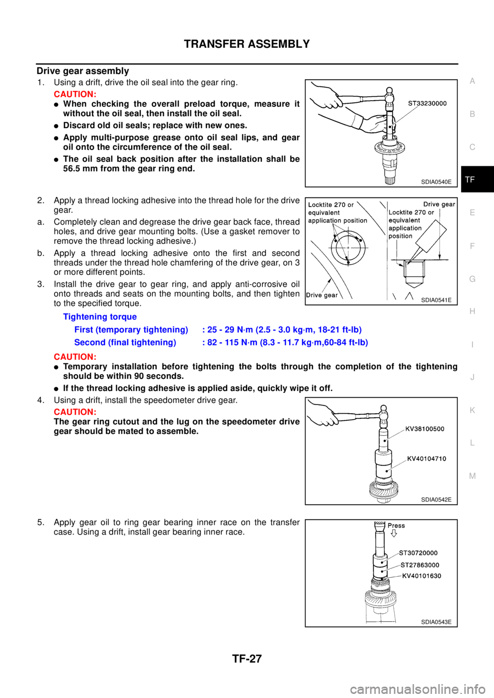
Drive gear assembly
1. Using a drift, drive the oil seal into the gear ring.
CAUTION:
lWhen checking the overall preload torque, measure it
without the oil seal, then install the oil seal.
lDiscard old oil seals; replace with new ones.
lApply multi-purpose grease onto oil seal lips, and gear
oil onto the circumference of the oil seal.
lThe oil seal back position after the installation shall be
56.5 mm from the gear ring end.
2. Apply a thread locking adhesive into the thread hole for the drive
gear.
a. Completely clean and degrease the drive gear back face, thread
holes, and drive gear mounting bolts. (Use a gasket remover to
remove the thread locking adhesive.)
b. Apply a thread locking adhesive onto the first and second
threads under the thread hole chamfering of the drive gear, on 3
or more different points.
3. Install the drive gear to gear ring, and apply anti-corrosive oil
onto threads and seats on the mounting bolts, and then tighten
to the specified torque.
CAUTION:
lTemporary installation before tightening the bolts through the completion of the tightening
should be within 90 seconds.
lIf the thread locking adhesive is applied aside, quickly wipe it off.
4. Using a drift, install the speedometer drive gear.
CAUTION:
The gear ring cutout and the lug on the speedometer drive
gear should be mated to assemble.
5. Apply gear oil to ring gear bearing inner race on the transfer
case. Using a drift, install gear bearing inner race.
SDIA0540E
Tightening torque
First (temporary tightening) : 25 - 29 N·m (2.5 - 3.0 kg·m, 18-21 ft-lb)
Second (final tightening) : 82 - 115 N·m (8.3 - 11.7 kg·m,60-84 ft-lb)
SDIA0541E
SDIA0542E
SDIA0543E
Page 2998 of 3066
TF-28
TRANSFER ASSEMBLY
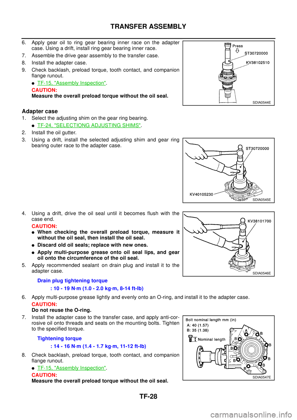
6. Apply gear oil to ring gear bearing inner race on the adapter
case. Using a drift, install ring gear bearing inner race.
7. Assemble the drive gear assembly to the transfer case.
8. Install the adapter case.
9. Check backlash, preload torque, tooth contact, and companion
flange runout.
lTF-15, "Assembly Inspection".
CAUTION:
Measure the overall preload torque without the oil seal.
Adapter case
1. Select the adjusting shim on the gear ring bearing.
lTF-24, "SELECTIONG ADJUSTING SHIMS".
2. Install the oil gutter.
3. Using a drift, install the selected adjusting shim and gear ring
bearing outer race to the adapter case.
4. Using a drift, drive the oil seal until it becomes flush with the
case end.
CAUTION:
lWhen checking the overall preload torque, measure it
without the oil seal, then install the oil seal.
lDiscard old oil seals; replace with new ones.
lApply multi-purpose grease onto oil seal lips, and gear
oil onto the circumference of the oil seal.
5. Apply recommended sealant on drain plug and install it to the
adapter case.
6. Apply multi-purpose grease lightly and evenly onto an O-ring, and install it to the adapter case.
CAUTION:
Do not reuse the O-ring.
7. Install the adapter case to the transfer case, and apply anti-cor-
rosive oil onto threads and seats on the mounting bolts. Tighten
to the specified torque.
8. Check backlash, preload torque, tooth contact, and companion
flange runout.
lTF-15, "Assembly Inspection".
CAUTION:
Measure the overall preload torque without the oil seal.
SDIA0544E
SDIA0545E
Drain plug tightening torque
: 10 - 19 N·m (1.0 - 2.0 kg·m, 8-14 ft-lb)
Tightening torque
: 14 - 16 N·m (1.4 - 1.7 kg·m, 11-12 ft-lb)
SDIA0546E
SDIA0547E