2003 NISSAN X-TRAIL service indicator
[x] Cancel search: service indicatorPage 2256 of 3066
PRECAUTIONS
GI-3
PRECAUTIONSPFP:00001
DescriptionEAS000FN
Observe the following precautions to ensure safe and proper servicing. These precautions are not
described in each individual section.
Precautions for Supplemental Restraint System (SRS) “AIR BAG” and “SEAT
BELT PRE-TENSIONER”
EAS000FO
The Supplemental Restraint System such as “AIR BAG” and “SEAT BELT PRE-TENSIONER”, used along
with a front seat belt, helps to reduce the risk or severity of injury to the driver and front passenger for certain
types of collision. Information necessary to service the system safely is included in the SRS and SB section of
this Service Manual.
WA RN ING:
lTo avoid rendering the SRS inoperative, which could increase the risk of personal injury or death
in the event of a collision which would result in air bag inflation, all maintenance must be per-
formed by an authorized NISSAN/INFINITI dealer.
lImproper maintenance, including incorrect removal and installation of the SRS, can lead to per-
sonal injury caused by unintentional activation of the system. For removal of Spiral Cable and Air
Bag Module, see the SRS section.
lDo not use electrical test equipment on any circuit related to the SRS unless instructed to in this
Service Manual. SRS wiring harnesses can be identified by yellow harness connectors.
Precautions for NATS (NISSAN ANTI-THEFT SYSTEM)EAS000FP
NATS will immobilize the engine if someone tries to start it without the registered key of NATS.
Both of the originally supplied ignition key IDs have been NATS registered.
The security indicator is located on the instrument panel. The indicator blinks when the immobilizer system is
functioning.
Therefore, NATS warns outsiders that the vehicle is equipped with the anti-theft system.
lWhen NATS detects trouble, the security indicator lamp lights up while ignition switch is in "ON" position.
This lighting up indicates that the anti-theft is not functioning, so prompt service is required.
lWhen servicing NATS (trouble diagnoses, system initialization and additional registration of other NATS
ignition key IDs), CONSULT-II hardware and CONSULT-II NATS software is necessary.
Regarding the procedures of NATS initialization and NATS ignition key ID registration, refer to CONSULT-
II operation manual, NATS.
Therefore, CONSULT-II NATS software (program card and operation manual) must be kept strictly con-
fidential to maintain the integrity of the anti-theft function.
lWhen servicing NATS (trouble diagnoses, system initialization and additional registration of other NATS
ignition key IDs), it may be necessary to re-register original key identification. Therefore, be sure to
receive all keys from vehicle owner. A maximum of four or five key IDs can be registered into NATS.
lWhen failing to start the engine first time using the key of NATS, start as follows.
1. Leave the ignition key in "ON" position for approximately 5 seconds.
2. Turn ignition key to "OFF" or "LOCK" position and wait approximately 5 seconds.
3. Repeat step 1 and 2 again.
4. Restart the engine while keeping the key separate from any others on key-chain.
Page 2302 of 3066

TERMINOLOGY
GI-49
Nonvolatile random access memory NVRAM ***
On board diagnostic system OBD system Self-diagnosis
Open loop OL Open loop
Oxidation catalyst OC Catalyst
Oxidation catalytic converter system OC system ***
Oxygen sensor O2S Exhaust gas sensor
Park position switch *** Park switch
Park/neutral position switch PNP switchPark/neutral switch
Inhibitor switch
Neutral position switch
Periodic trap oxidizer system PTOX system ***
Positive crankcase ventilation PCV Positive crankcase ventilation
Positive crankcase ventilation valve PCV valve PCV valve
Powertrain control module PCM ***
Programmable read only memory PROM ***
Pulsed secondary air injection control sole-
noid valvePAIRC solenoid valve AIV control solenoid valve
Pulsed secondary air injection system PAIR system Air induction valve (AIV) control
Pulsed secondary air injection valve PAIR valve Air induction valve
Random access memory RAM ***
Read only memory ROM ***
Scan tool ST ***
Secondary air injection pump AIR pump ***
Secondary air injection system AIR system ***
Sequential multiport fuel injection system SFI system Sequential fuel injection
Service reminder indicator SRI ***
Simultaneous multiport fuel injection sys-
tem*** Simultaneous fuel injection
Smoke puff limiter system SPL system ***
Supercharger SC ***
Supercharger bypass SCB ***
System readiness test SRT ***
Thermal vacuum valve TVV Thermal vacuum valve
Three way catalyst TWC Catalyst
Three way catalytic converter system TWC system ***
Three way + oxidation catalyst TWC + OC Catalyst
Three way + oxidation catalytic converter
systemTWC + OC system ***
Throttle body TBThrottle chamber
SPI body
Throttle body fuel injection system TBI system Fuel injection control
Throttle position TP Throttle position
Throttle position sensor TPS Throttle sensor
Throttle position switch TP switch Throttle switchNEW TERMNEW ACRONYM /
ABBREVIATIONOLD TERM
Page 2359 of 3066
IDX-2
ALPHABETICAL INDEX
Numerics
4WD mode switch ...................................TF-53
,TF-57
4WD shift indicator lamp .........................TF-32,TF-54
4WD solenoid valve ................................TF-49,TF-51
4WD warning lamp ..........TF-32,TF-40,TF-55,TF-58
A
A/C air flow .........................................ATC-28
,MTC-5
A/C component layout .....................................ATC-20
A/C compressor clutch removal and installation ...........
ATC-129
A/C compressor precaution ...............................ATC-7
A/C compressor special service tool ................ATC-11
A/C diagnostic work flow (auto A/C) ................ATC-30
A/C HFC134a (R134a) system precaution ........ATC-4
A/C HFC134a (R134a) system service procedure .......
ATC-123
A/C HFC134a (R134a) system service tools ...ATC-12
A/C HFC134a system service equipment precaution ...
ATC-8
A/C lubricant (R134a) ......................................ATC-21
A/C operational check .........................ATC-51,MTC-7
A/C performance test diagnoses .....................ATC-83
A/C reray ..........................................................ATC-80
A/C self-diagnoses (auto A/C) .........................ATC-42
A/C service data specification ........................ATC-143
A/C system description (auto A/C) ...................ATC-24
A/C trouble diagnoses (auto A/C) .......ATC-30,MTC-3
A/C, A - Wiring diagram ...................................ATC-35
A/CCUT - Wiring diagram ................................EC-824
A/T - Wiring diagram - AT - FTS ......................AT-138
A/T - Wiring diagram - AT - MAIN ....................AT-389
A/T - Wiring diagram - AT - PNP/SW ...............AT-132
A/T - Wiring diagram - AT - VSS A/T .AT-144,AT-394
A/T fluid checking ..................................AT-13,MA-36
A/T fluid replacement .............................AT-13,MA-36
A/T fluid temperature sensor ...........................AT-141
A/T IND - Wiring diagram ....................................DI-51
A/T indicator ........................................................DI-51
A/T shift lock system ........................................AT-446
A/T shift lock system - Wiring diagram ............AT-447
A/T trouble diagnoses ..........................AT-56,AT-279
A/T Wiring diagram - AT - ENG SS ...AT-148,AT-433
A/T Wiring diagram AT - 1ST ...........................AT-154
A/T Wiring diagram AT - 2ND ..........................AT-161
A/T Wiring diagram AT - 3RD ..........................AT-168
A/T Wiring diagram AT - 4TH ..........................AT-175
A/T Wiring diagram AT - BA/FTS .......AT-218,AT-428
A/T Wiring diagram AT - LPSV ..........AT-188,AT-438
A/T Wiring diagram AT - OVRCSV ....AT-210,AT-418
A/T Wiring diagram AT - SSV/A .........AT-195,AT-408
A/T Wiring diagram AT - SSV/B .........AT-200,AT-413
A/T Wiring diagram AT - TCV ............AT-183,AT-423
A/T Wiring diagram AT - TPS ............AT-205,AT-403
A/T Wiring diagrawm AT - VSSMTR ..AT-224,AT-399
ABS - Wiring diagram .....................................BRC-12
Absolute pressure sensor ................................EC-749
Accelerator control system ...............................ACC-2
Accelerator pedal position (APP) sensor ........EC-154,
EC-484
,EC-715
Accelerator pedal released position learning ...EC-664
Accelerator pedal released position switch ......EC-783
Actuator relay .....................................................TF-51
Aiming adjustment ...............................................LT-4
Air bag ..............................................................SRS-3
Air bag disposal ..............................................SRS-40
Air bleeding (hydraulic clutch) ..............................CL-8
Air bleeding for brake system ............................BR-10
Air cleaner and air duct(QR20DE) ....................EM-15
Air cleaner and air duct(YD22DDTi) ...............EM-112
Air cleaner filter replacement(QR20DE) ...........MA-23
Air cleaner filter replacement(YD22DDTi) .........MA-31
Air cleaner filter(QR20DE) ................................EM-15
Air cleaner filter(YD22DDTi) ...........................EM-112
Air conditioner cut control .....EC-27,EC-392,EC-662
Air flow meter - See Mass air flow sensor .......EC-130,
EC-260
,EC-463
Air mix door control linkage adjustment .........ATC-64,
ATC-119
,MTC-9,MTC-28
Air mix. door motor .........................ATC-61,ATC-119
Air spoiler, rear ...................................................EI-21
Alternator ...........................................................SC-12
Ambient sensor .................ATC-93,ATC-95,ATC-105
Angular tightening application(QR20DE) ............EM-5
Angular tightening application(YD22DDTi) .....EM-102
Antenna - See Power antenna ...........................AV-15
APPS - Wiring diagram .......EC-156,EC-486,EC-717
APRSW - Wiring diagram ................................EC-785
Audio ....................................................................AV-3
Auto air conditioner - Wiring diagram .............ATC-35
Automatic amplifier ...........................ATC-41,ATC-53
Automatic transmission fluid replacement .......MA-35,
MA-37
Axle ...................................................................MA-41
B
Back door ...........................................................BL-60
Back door trim .....................................................EI-25
Back door window ..............................................GW-7
Back window ......................................................GW-7
BACK/L - Wiring diagram ...................................LT-28
Back-up lamp ..........................................LT-28,LT-42
Back-up lamp switch (M/T) ...............................MT-13
Basic inspection ....................EC-64,EC-412,EC-672
Battery .................................................................SC-3
Baulk ring (M/T) ....................................MT-19,MT-24
Blower motor .....ATC-67,ATC-73,ATC-111,MTC-13,
MTC-17
,MTC-20
Blower resistor ................................................MTC-21
Blower unit .....................................ATC-109,MTC-20
Brake booster ....................................................BR-17
Brake fluid change ...............................................BR-9
Brake fluid level ................................................MA-38
Page 2767 of 3066
STEERING WHEEL
PS-7
C
D
E
F
H
I
J
K
L
MA
B
PS
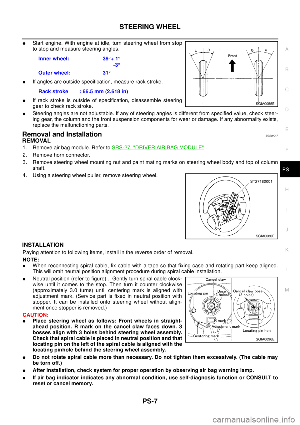
lStart engine. With engine at idle, turn steering wheel from stop
to stop and measure steering angles.
lIf angles are outside specification, measure rack stroke.
lIf rack stroke is outside of specification, disassemble steering
gear to check rack stroke.
lSteering angles are not adjustable. If any of steering angles is different from specified value, check steer-
ing gear, the column and the front suspension components for wear or damage. If any abnormality exists,
replace the malfunctioning parts.
Removal and InstallationEGS0004F
REMOVAL
1. Remove air bag module. Refer toSRS-27, "DRIVER AIR BAG MODULE".
2. Remove horn connector.
3. Remove steering wheel mounting nut and paint mating marks on steering wheel body and top of column
shaft.
4. Using a steering wheel puller, remove steering wheel.
INSTALLATION
Paying attention to following items, install in the reverse order of removal.
NOTE:
lWhen reconnecting spiral cable, fix cable with a tape so that fixing case and rotating part keep aligned.
This will omit neutral position alignment procedure during spiral cable installation.
lNeutral position (refer to figure)... Gently turn spiral cable clock-
wise until it comes to the stop. Then turn it counter clockwise
(approximately 3.0 turns) until centering mark is aligned with
adjustment mark. (Service part is fixed in neutral position with
stopper. It can be installed onto steering wheel without align-
ment once stopper is removed.)
CAUTION:
lPlace steering wheel as follows: Front wheels in straight-
ahead position. R mark on the cancel claw faces down. 3
bosses align with 3 holes behind steering wheel assembly.
Check that spiral cable is placed in neutral position and that
locating pin on the left of the spiral cable is aligned with the
locating pinhole behind the steering wheel assembly.
lDo not rotate spiral cable more than necessary. Do not tighten them excessively. (The cable may
be torn off.)
lAfter installation, check system for proper operation by observing air bag warning lamp.
lIf air bag indicator indicates any abnormal condition, use self-diagnosis function or CONSULT to
reset or cancel memory.Inner wheel: 39°+1°
-3°
Outer wheel: 31°
Rack stroke : 66.5 mm (2.618 in)
SGIA0055E
SGIA0080E
SGIA0096E
Page 2873 of 3066
SC-1
STARTING & CHARGING SYSTEM
K ELECTRICAL
CONTENTS
C
D
E
F
G
H
I
J
L
M
SECTION
A
B
SC
STARTING & CHARGING SYSTEM
PRECAUTIONS .......................................................... 2
Precautions for Supplemental Restraint System
(SRS) “AIR BAG” and “SEAT BELT PRE-TEN-
SIONER” .................................................................. 2
Wiring Diagrams and Trouble Diagnosis .................. 2
BATTERY .................................................................... 3
How to Handle Battery ............................................. 3
METHODS OF PREVENTING OVER-DIS-
CHARGE ............................................................... 3
CHECKING ELECTROLYTE LEVEL .................... 3
SPECIFIC GRAVITY CHECK ............................... 4
Battery Test and Charging Chart .............................. 5
CHART I ................................................................ 5
CHART II ............................................................... 6
A: SLOW CHARGE ............................................... 7
B: STANDARD CHARGE ...................................... 8
C: QUICK CHARGE ............................................ 10
Removal and Installation .........................................11
CHARGING SYSTEM ............................................... 12
System Description ................................................ 12
Wiring Diagram — CHARGE — ............................. 13
Trouble Diagnoses ................................................. 14
WITH IC REGULATOR ....................................... 14
MALFUNCTION INDICATOR .............................. 14
Removal and Installation ........................................ 14
REMOVAL (QR ENGINE MODELS) ................... 14
REMOVAL (YD ENGINE MODELS) ................... 15
INSTALLATION ................................................... 15
Disassembly and Assembly ................................... 16
............................................................................ 16
............................................................................ 17
Disassembly ........................................................... 17
REAR COVER .................................................... 17REAR BEARING ................................................. 18
Inspection ............................................................... 18
ROTOR CHECK .................................................. 18
BRUSH CHECK .................................................. 18
PULLEY CHECK(WITH CLUTCH TYPE) ............ 18
STATOR CHECK ................................................. 19
Assembly ................................................................ 19
RING FITTING IN REAR BEARING .................... 19
REAR COVER INSTALLATION ........................... 19
STARTING SYSTEM ................................................. 21
System Description ................................................. 21
M/T MODELS ...................................................... 21
A/T MODELS ....................................................... 21
Wiring Diagram — START —/M/T models ............. 22
Wiring Diagram — START —/A/T models .............. 23
Trouble Diagnoses ................................................. 24
Removal and Installation ........................................ 25
REMOVAL ........................................................... 25
INSTALLATION ................................................... 25
Disassembly and Assembly .................................... 26
Inspection ............................................................... 28
MAGNETIC SWITCH CHECK ............................. 28
PINION/CLUTCH CHECK ................................... 29
BRUSH CHECK .................................................. 29
YOKE CHECK ..................................................... 30
ARMATURE CHECK ........................................... 31
Assembly ................................................................ 32
PINION PROTRUSION LENGTH ADJUST-
MENT .................................................................. 32
SERVICE DATA AND SPECIFICATIONS (SDS) ...... 34
Battery .................................................................... 34
Starter ..................................................................... 34
Alternator ................................................................ 34
Page 2971 of 3066
TF-1
TRANSFER
D DRIVELINE/AXLE
CONTENTS
C
E
F
G
H
I
J
K
L
M
SECTION
A
B
TF
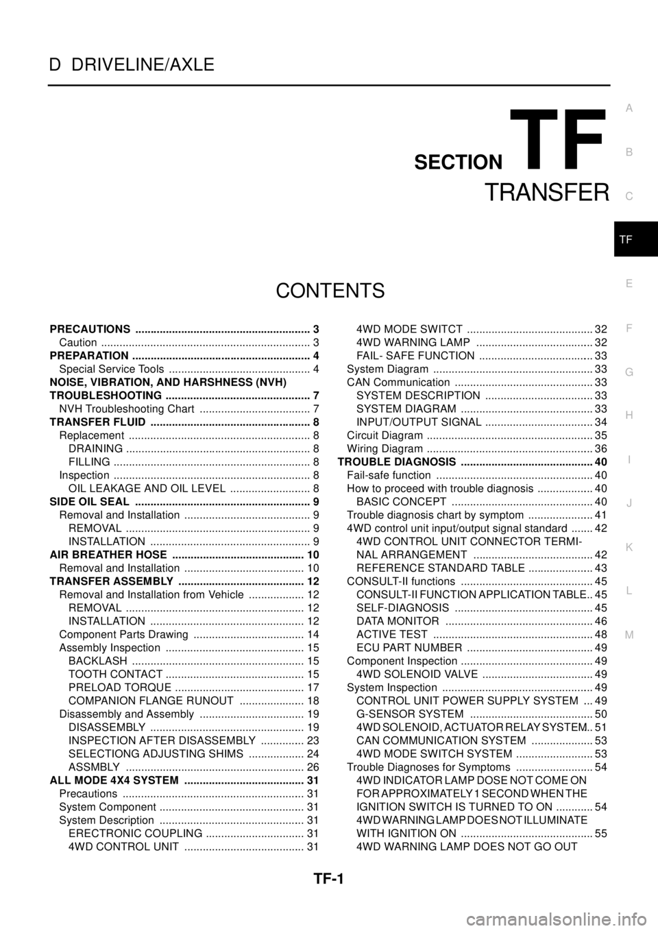
TRANSFER
PRECAUTIONS .......................................................... 3
Caution ..................................................................... 3
PREPARATION ........................................................... 4
Special Service Tools ............................................... 4
NOISE, VIBRATION, AND HARSHNESS (NVH)
TROUBLESHOOTING ................................................ 7
NVH Troubleshooting Chart ..................................... 7
TRANSFER FLUID ..................................................... 8
Replacement ............................................................ 8
DRAINING ............................................................. 8
FILLING ................................................................. 8
Inspection ................................................................. 8
OIL LEAKAGE AND OIL LEVEL ........................... 8
SIDE OIL SEAL .......................................................... 9
Removal and Installation .......................................... 9
REMOVAL ............................................................. 9
INSTALLATION ..................................................... 9
AIR BREATHER HOSE ............................................ 10
Removal and Installation ........................................ 10
TRANSFER ASSEMBLY .......................................... 12
Removal and Installation from Vehicle ................... 12
REMOVAL ........................................................... 12
INSTALLATION ................................................... 12
Component Parts Drawing ..................................... 14
Assembly Inspection .............................................. 15
BACKLASH ......................................................... 15
TOOTH CONTACT .............................................. 15
PRELOAD TORQUE ........................................... 17
COMPANION FLANGE RUNOUT ...................... 18
Disassembly and Assembly ................................... 19
DISASSEMBLY ................................................... 19
INSPECTION AFTER DISASSEMBLY ............... 23
SELECTIONG ADJUSTING SHIMS ................... 24
ASSMBLY ........................................................... 26
ALL MODE 4X4 SYSTEM ........................................ 31
Precautions ............................................................ 31
System Component ................................................ 31
System Description ................................................ 31
ERECTRONIC COUPLING ................................. 31
4WD CONTROL UNIT ........................................ 314WD MODE SWITCT .......................................... 32
4WD WARNING LAMP ....................................... 32
FAIL- SAFE FUNCTION ...................................... 33
System Diagram ..................................................... 33
CAN Communication .............................................. 33
SYSTEM DESCRIPTION .................................... 33
SYSTEM DIAGRAM ............................................ 33
INPUT/OUTPUT SIGNAL .................................... 34
Circuit Diagram ....................................................... 35
Wiring Diagram ....................................................... 36
TROUBLE DIAGNOSIS ............................................ 40
Fail-safe function .................................................... 40
How to proceed with trouble diagnosis ................... 40
BASIC CONCEPT ............................................... 40
Trouble diagnosis chart by symptom ...................... 41
4WD control unit input/output signal standard ........ 42
4WD CONTROL UNIT CONNECTOR TERMI-
NAL ARRANGEMENT ........................................ 42
REFERENCE STANDARD TABLE ...................... 43
CONSULT-II functions ............................................ 45
CONSULT-II FUNCTION APPLICATION TABLE... 45
SELF-DIAGNOSIS .............................................. 45
DATA MONITOR ................................................. 46
ACTIVE TEST ..................................................... 48
ECU PART NUMBER .......................................... 49
Component Inspection ............................................ 49
4WD SOLENOID VALVE ..................................... 49
System Inspection .................................................. 49
CONTROL UNIT POWER SUPPLY SYSTEM .... 49
G-SENSOR SYSTEM ......................................... 50
4WD SOLENOID, ACTUATOR RELAY SYSTEM... 51
CAN COMMUNICATION SYSTEM ..................... 53
4WD MODE SWITCH SYSTEM .......................... 53
Trouble Diagnoses for Symptoms .......................... 54
4WD INDICATOR LAMP DOSE NOT COME ON
FORAPPROXIMATELY1SECONDWHENTHE
IGNITION SWITCH IS TURNED TO ON ............. 54
4WD WARNING LAMP DOES NOT ILLUMINATE
WITH IGNITION ON ............................................ 55
4WD WARNING LAMP DOES NOT GO OUT
Page 2972 of 3066

TF-2
SEVERAL SECONDS AFTER ENGINE
STARTED.(4WD MODE INDICATOR LAMP
GOES OUT) ........................................................ 55
HEAVY TIGHT-CORNER BRAKING SYMPTOM
OCCURS WHEN THE VEHICLE IS DRIVEN IN
AUTO MODE AND THE STEERING WHEEL IS
TURNED FULLY TO EITHER SIDE AFTER THE
ENGINE IS STARTED ......................................... 56
4WD MODES CANNOT BE SWITCHED AFTER
ENGINE IS STARTED ......................................... 57
WHILE DRIVING, 4WD WARNING LAMP
FLASHES RAPIDLY.(WHEN IT FLASHERSFOR
APPROX. ONE MINUTE, THEN DOES NOT
ILLUMINATE.) ..................................................... 57
WHILE DRIVING, 4WD WARNING LAMP
FLASHES SLOWLY. (WHEN IT CONTINUES TO
ILLUMINATE UNTIL ENGINE TURNS OFF.) ...... 58
VEHICLE DOES NOT ENTER 4WD MODEEVEN THOUGH 4WD WARNING LAMP IS OFF.... 58
TIGHT-CONER BRAKING SYMPTOM OCCURS
WHEN THE VEHICLE IS STARTED IN AUTO
WARNING LAMP REMAIN OFF). .......................58
4WD ACTUATOR RELAY (4WD SOLENOID
ACTUATOR RELAY) TURNS ON/OFF FRE-
QUENTLY ............................................................58
SERVICE DATA AND SPECIFICATIONS (SDS) ......60
General Specifications ............................................60
Inspection and Adjustment ......................................60
PRELOAD TORQUE BEFORE DISASSEMBLY...60
PRELOAD TORQUE AFTER DISASSEMBLY
AND REASSEMBLY ............................................60
BACKLSH ............................................................60
SELECTIVE PARTS ............................................60
PINION SLEEVE SHIM ........................................61
Page 3035 of 3066
ROAD WHEEL
WT-3
C
D
F
G
H
I
J
K
L
MA
B
WT
ROAD WHEELPFP:40300
InspectionEES000J2
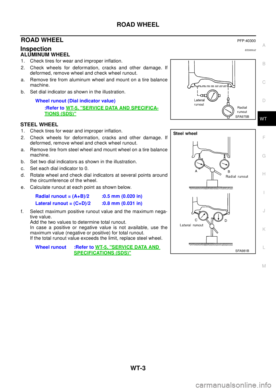
ALUMINUM WHEEL
1. Check tires for wear and improper inflation.
2. Check wheels for deformation, cracks and other damage. If
deformed, remove wheel and check wheel runout.
a. Remove tire from aluminum wheel and mount on a tire balance
machine.
b. Set dial indicator as shown in the illustration.
STEEL WHEEL
1. Check tires for wear and improper inflation.
2. Check wheels for deformation, cracks and other damage. If
deformed, remove wheel and check wheel runout.
a. Remove tire from steel wheel and mount wheel on a tire balance
machine.
b. Set two dial indicators as shown in the illustration.
c. Set each dial indicator to 0.
d. Rotate wheel and check dial indicators at several points around
the circumference of the wheel.
e. Calculate runout at each point as shown below.
f. Select maximum positive runout value and the maximum nega-
tive value.
Add the two values to determine total runout.
In case a positive or negative value is not available, use the
maximum value (negative or positive) for total runout.
If the total runout value exceeds the limit, replace steel wheel.Wheel runout (Dial indicator value)
:Refer toWT-5, "
SERVICE DATA AND SPECIFICA-
TIONS (SDS)"SFA975B
Radial runout = (A+B)/2 :0.5 mm (0.020 in)
Lateral runout = (C+D)/2 :0.8 mm (0.031 in)
Wheel runout :Refer toWT-5, "
SERVICE DATA AND
SPECIFICATIONS (SDS)"SFA981B