2003 NISSAN X-TRAIL ECU
[x] Cancel search: ECUPage 745 of 3066

BL-1
BODY, LOCK & SECURITY SYSTEM
IBODY
CONTENTS
C
D
E
F
G
H
J
K
L
M
SECTION
A
B
BL
BODY, LOCK & SECURITY SYSTEM
PRECAUTIONS .......................................................... 3
Precautions .............................................................. 3
HOOD ......................................................................... 4
Fitting Adjustment .................................................... 4
FRONT END HEIGHT ADJUSTMENT AND LAT-
ERAL/LONGITUDIAL CLEARANCE ADJUST-
MENT .................................................................... 4
SURFACE HEIGHT ADJUSTMENT ..................... 4
Removal and Installation of Hood Assembly ............ 5
Removal and Installation of Hood Lock Control ....... 6
REMOVAL ............................................................. 6
INSTALLATION ..................................................... 7
Hood Lock Control Inspection .................................. 7
DOOR ......................................................................... 8
Fitting Adjustment .................................................... 8
FRONT DOOR ...................................................... 8
REAR DOOR ........................................................ 8
STRIKER ADJUSTMENT ..................................... 9
Removal and Installation .......................................... 9
Door Weatherstrip .................................................. 10
POWER DOOR LOCK SYSTEM ...............................11
System Description .................................................11
OPERATION ........................................................11
Component Parts and Harness Connector Location....11
Schematic .............................................................. 12
Wiring Diagram — D/LOCK — ............................... 13
Terminal and Reference Value for Time Control Unit... 17
Symptom Chart ...................................................... 17
Power Supply and Ground Circuit Check ............... 18
Door Lock/Unlock Switch Check ............................ 18
Door Key Cylinder Switch Check ........................... 19
Door Lock Actuator Check ..................................... 20
Door Switch Check ................................................. 21
Door Unlock Sensor Check .................................... 22
Key Switch Check .................................................. 23
POWER DOOR LOCK — SUPER LOCK — ............ 24
System Description ................................................ 24
OUTLINE ............................................................. 24
OPERATION ....................................................... 24
Schematic .............................................................. 26Wiring Diagram — S/LOCK — ............................... 27
Terminal and Reference Value for Time Control Unit... 33
Trouble Diagnoses ................................................. 34
PRELIMINARY CHECK ....................................... 34
SYMPTOM CHART ............................................. 35
Power Supply and Ground Circuit Check ............... 36
Door Lock/Unlock Switch Check ............................ 36
Door Key Cylinder Switch Check ............................ 37
Door Lock Actuator Check ...................................... 38
Door Switch Check ................................................. 39
Door Unlock Sensor Check .................................... 40
Key Switch Check ................................................... 41
Super Lock Actuator Check .................................... 42
NATS Release Signal Check .................................. 43
Ignition Switch “ON” Circuit Check ......................... 44
Remote Controller Signal Check ............................ 44
MULTI-REMOTE CONTROL SYSTEM ..................... 45
Component Parts and Harness Connector Location... 45
System Description ................................................. 45
FUNCTION .......................................................... 45
LOCK OPERATION ............................................. 45
UNLOCK OPERATION ........................................ 46
HAZARD REMINDER ......................................... 46
MULTI-REMOTE CONTROLLER ID CODE
ENTRY ................................................................ 46
Wiring Diagram — MULTI — .................................. 47
Terminal and Reference Value for Multi-remote
Control Unit ............................................................. 49
Symptom Chart ....................................................... 49
Remote Controller Battery Check ........................... 49
Power Supply and Ground Circuit Check ............... 50
Hazard Reminder Check ........................................ 51
ID Code Entry Procedure ....................................... 52
Remote Controller Battery Replacement ................ 53
FRONT DOOR LOCK ............................................... 54
Component Parts Location ..................................... 54
Inspection and Adjustment ..................................... 54
OUT SIDE HANDLE ROD ADJUSTMENT .......... 54
Removal and Installation ........................................ 54
REMOVAL ........................................................... 54
Page 749 of 3066
HOOD
BL-5
C
D
E
F
G
H
J
K
L
MA
B
BL
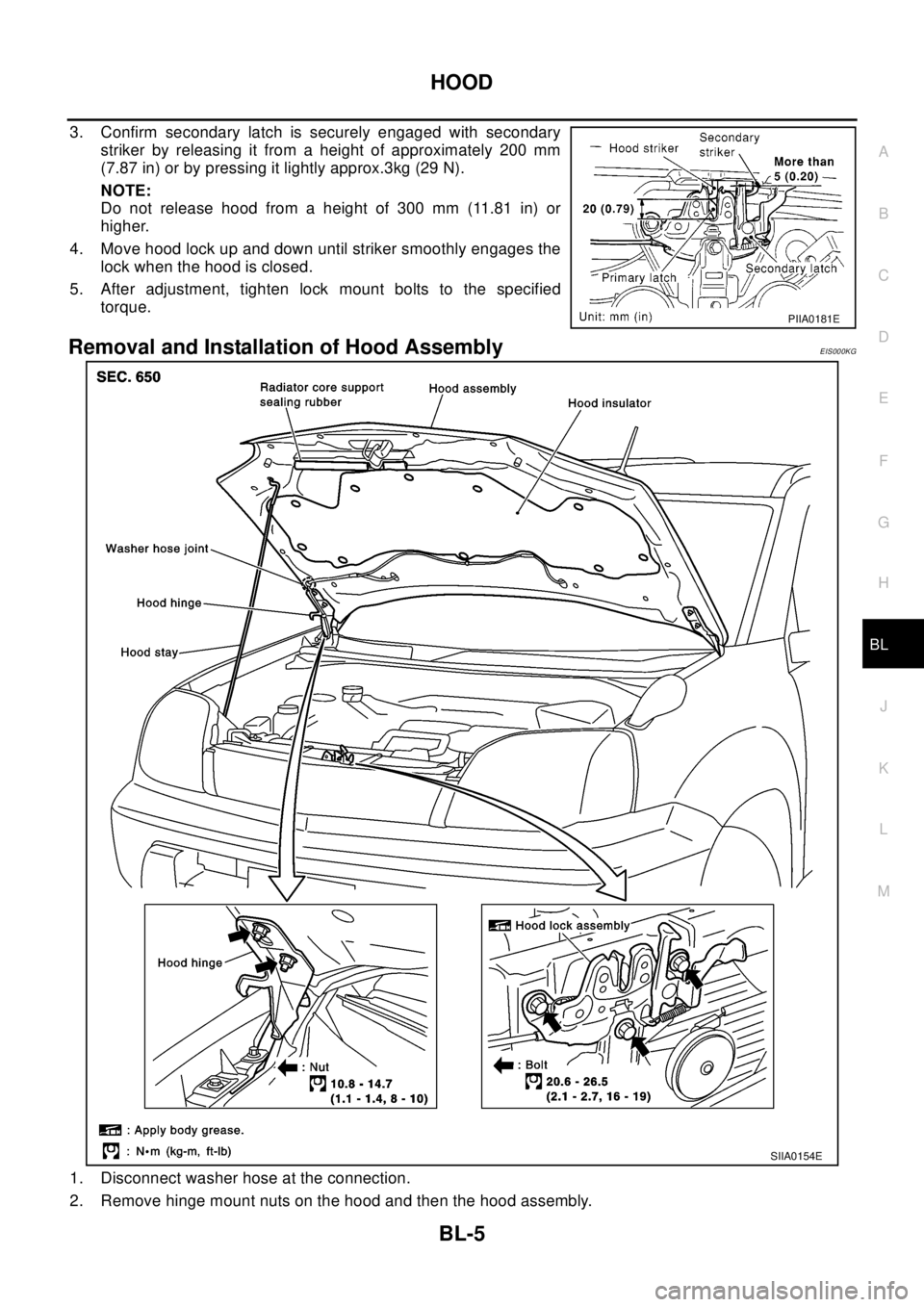
3. Confirm secondary latch is securely engaged with secondary
striker by releasing it from a height of approximately 200 mm
(7.87 in) or by pressing it lightly approx.3kg (29 N).
NOTE:
Do not release hood from a height of 300 mm (11.81 in) or
higher.
4. Move hood lock up and down until striker smoothly engages the
lock when the hood is closed.
5. After adjustment, tighten lock mount bolts to the specified
torque.
Removal and Installation of Hood AssemblyEIS000KG
1. Disconnect washer hose at the connection.
2. Remove hinge mount nuts on the hood and then the hood assembly.
PIIA0181E
SIIA0154E
Page 751 of 3066
HOOD
BL-7
C
D
E
F
G
H
J
K
L
MA
B
BL
INSTALLATION
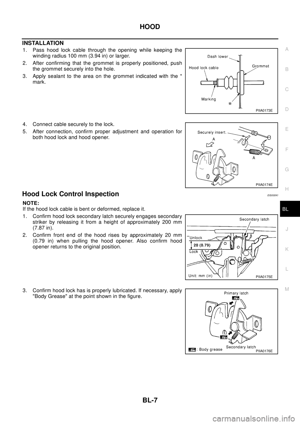
1. Pass hood lock cable through the opening while keeping the
winding radius 100 mm (3.94 in) or larger.
2. After confirming that the grommet is properly positioned, push
the grommet securely into the hole.
3. Apply sealant to the area on the grommet indicated with the *
mark.
4. Connect cable securely to the lock.
5. After connection, confirm proper adjustment and operation for
both hood lock and hood opener.
Hood Lock Control InspectionEIS000KI
NOTE:
If the hood lock cable is bent or deformed, replace it.
1. Confirm hood lock secondary latch securely engages secondary
striker by releasing it from a height of approximately 200 mm
(7.87 in).
2. Confirm front end of the hood rises by approximately 20 mm
(0.79 in) when pulling the hood opener. Also confirm hood
opener returns to the original position.
3. Confirm hood lock has is properly lubricated. If necessary, apply
"Body Grease" at the point shown in the figure.
PIIA0173E
PIIA0174E
PIIA0175E
PIIA0176E
Page 800 of 3066
BL-56
FRONT DOOR LOCK
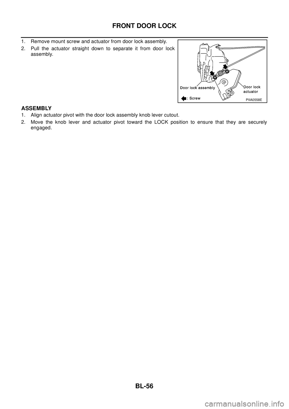
1. Remove mount screw and actuator from door lock assembly.
2. Pull the actuator straight down to separate it from door lock
assembly.
ASSEMBLY
1. Align actuator pivot with the door lock assembly knob lever cutout.
2. Move the knob lever and actuator pivot toward the LOCK position to ensure that they are securely
engaged.
PIIA0558E
Page 803 of 3066
REAR DOOR LOCK
BL-59
C
D
E
F
G
H
J
K
L
MA
B
BL
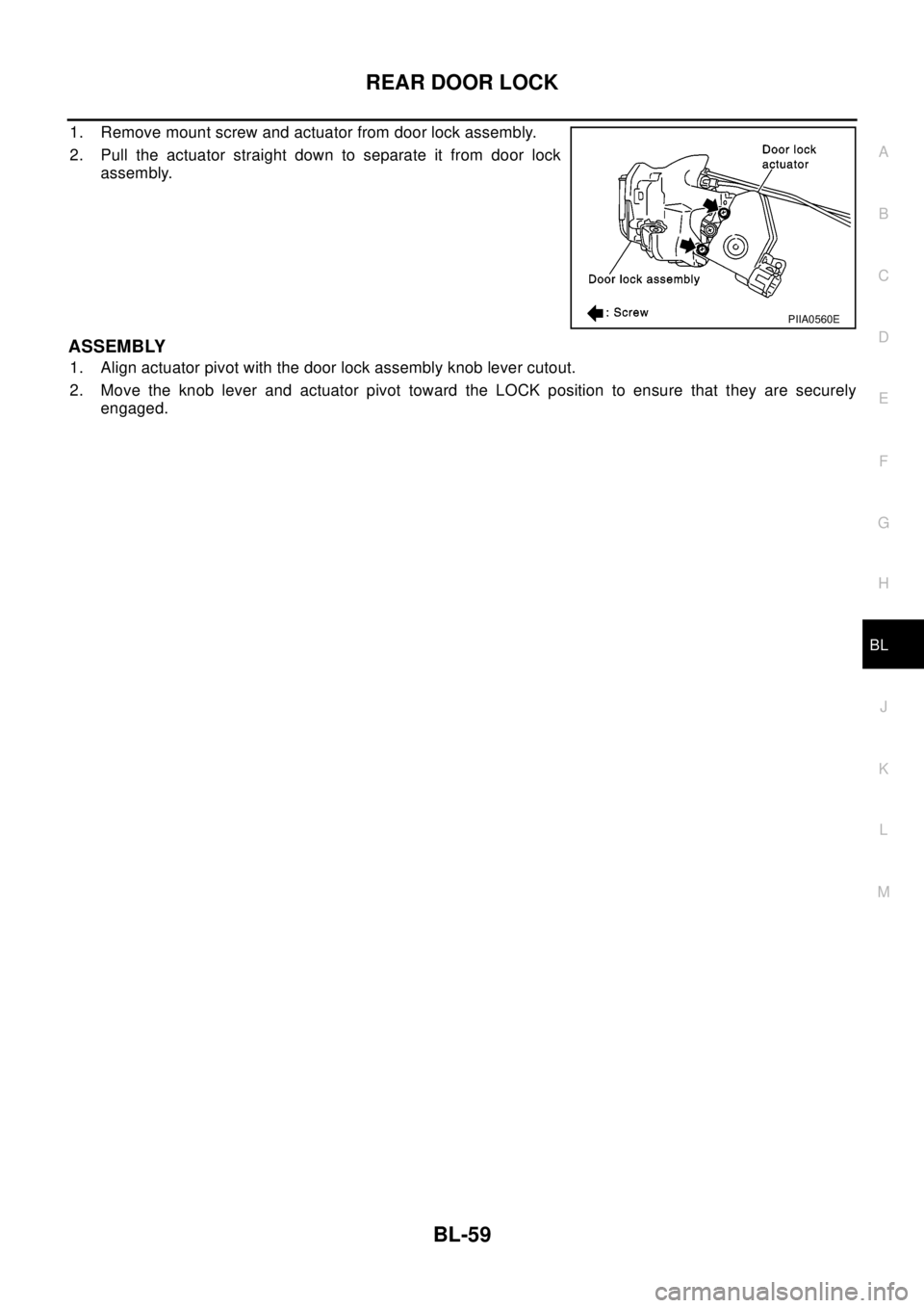
1. Remove mount screw and actuator from door lock assembly.
2. Pull the actuator straight down to separate it from door lock
assembly.
ASSEMBLY
1. Align actuator pivot with the door lock assembly knob lever cutout.
2. Move the knob lever and actuator pivot toward the LOCK position to ensure that they are securely
engaged.
PIIA0560E
Page 814 of 3066
BL-70
NATS (NISSAN ANTI-THEFT SYSTEM)
NATS (NISSAN ANTI-THEFT SYSTEM)
PFP:25386
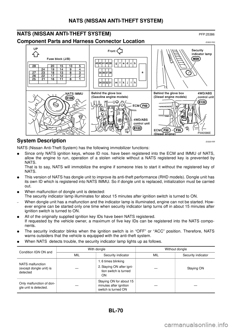
Component Parts and Harness Connector LocationEIS001RQ
System DescriptionEIS001RR
NATS (Nissan Anti-Theft System) has the following immobilizer functions:
lSince only NATS ignition keys, whose ID nos. have been registered into the ECM and IMMU of NATS,
allow the engine to run, operation of a stolen vehicle without a NATS registered key is prevented by
NATS.
That is to say, NATS will immobilize the engine if someone tries to start it without the registered key of
NATS.
lThis version of NATS has dongle unit to improve its anti-theft performance (RHD models). Dongle unit has
its own ID which is registered into NATS IMMU. So if dongle unit is replaced, initialization must be carried
out.
lWhen malfunction of dongle unit is detected:
The security indicator lamp illuminates for about 15 minutes after ignition switch is turned to ON.
–When dongle unit has a malfunction and the indicator lamp is illuminated, engine can not be started. How-
ever engine can be started only one time when security indicator lamp turns off in about 15 minutes after
ignition switch is turned to ON.
lAll of the originally supplied ignition key IDs have been NATS registered.
If requested by the vehicle owner, a maximum of five key IDs can be registered into the NATS compo-
nents.
lThe security indicator blinks when the ignition switch is in “OFF” or “ACC” position. Therefore, NATS
warns outsiders that the vehicle is equipped with the anti-theft system.
lWhen NATS detects trouble, the security indicator lamp lights up as follows.
PIIA0586E
Condition IGN ON andWith dongle Without dongle
MIL Security indicator MIL Security indicator
NATS malfunction
(except dongle unit) is
detected—1. 6 times blinking
2. Staying ON after igni-
tion switch is turned
ON—StayingON
Only malfunction of don-
gle unit is detected.—Staying ON for about 15
minutes after ignition
switch is turned ON——
Page 815 of 3066
NATS (NISSAN ANTI-THEFT SYSTEM)
BL-71
C
D
E
F
G
H
J
K
L
MA
B
BL
lNATS trouble diagnoses, system initialization and additional registration of other NATS ignition key IDs
must be carried out using CONSULT-II hardware and CONSULT-II NATS software.
Regarding the procedures of NATS initialization and NATS ignition key ID registration, refer to CONSULT-
II operation manual, NATS.
lWhen servicing a malfunction of the NATS (indicated by lighting up of Security Indicator Lamp) or
registering another NATS ignition key ID no., it may be necessary to re-register original key iden-
tification. Therefore, be sure to receive ALL KEYS from vehicle owner.
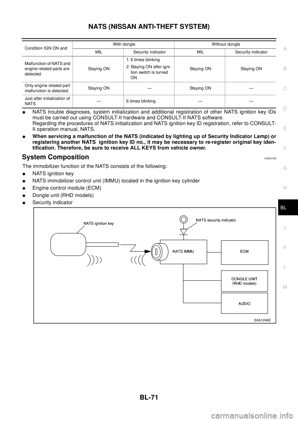
System CompositionEIS001RS
The immobilizer function of the NATS consists of the following:
lNATS ignition key
lNATS immobilizer control unit (IMMU) located in the ignition key cylinder
lEngine control module (ECM)
lDongle unit (RHD models)
lSecurity indicator
Malfunction of NATS and
engine related parts are
detected.Stay ing ON1. 6 times blinking
2. Staying ON after igni-
tion switch is turned
ONStaying ON Staying ON
Only engine related part
malfunction is detected.Stay ing ON — Sta y in g ON —
Just after initialization of
NATS— 6 times blinking — — Condition IGN ON andWith dongle Without dongle
MIL Security indicator MIL Security indicator
SIIA1246E
Page 819 of 3066
NATS (NISSAN ANTI-THEFT SYSTEM)
BL-75
C
D
E
F
G
H
J
K
L
MA
B
BL
NOTE:
lWhen any initialization is performed, all ID previously registered will be erased and all NATS igni-
tion keys must be registered again.
lThe engine cannot be started with an unregistered key. In this case, the system may show “DIFFERENCE
OF KEY” or “LOCK MODE” as a self-diagnostic result on the CONSULT-II screen.
lWhen initialization is performed for RHD models, security indicator will flash six times to demonstrate rec-
ognition of the dongle unit ID.
lIn rare case, “CHAIN OF ECM-IMMU” might be stored as a self-diagnostic result during key registration
procedure, even if the system is not malfunctioning.
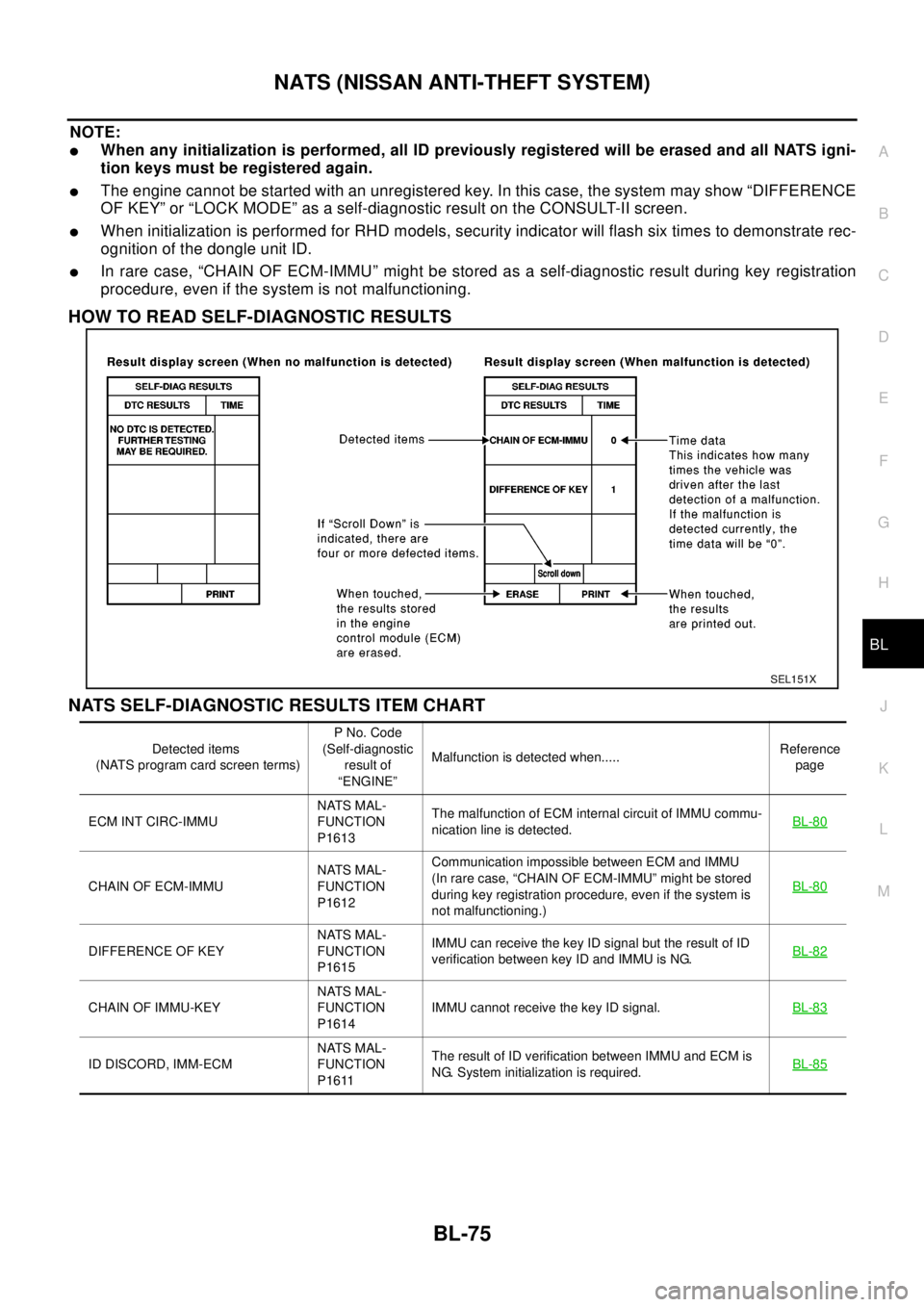
HOW TO READ SELF-DIAGNOSTIC RESULTS
NATS SELF-DIAGNOSTIC RESULTS ITEM CHART
SEL151X
Detected items
(NATS program card screen terms)P No. Code
(Self-diagnostic
result of
“ENGINE”Malfunction is detected when.....Reference
page
ECM INT CIRC-IMMUNATS MAL-
FUNCTION
P1613The malfunction of ECM internal circuit of IMMU commu-
nication line is detected.BL-80
CHAIN OF ECM-IMMUNATS MAL-
FUNCTION
P1612Communication impossible between ECM and IMMU
(In rare case, “CHAIN OF ECM-IMMU” might be stored
during key registration procedure, even if the system is
not malfunctioning.)BL-80
DIFFERENCE OF KEYNATS MAL-
FUNCTION
P1615IMMU can receive the key ID signal but the result of ID
verification between key ID and IMMU is NG.BL-82
CHAIN OF IMMU-KEYNATS MAL-
FUNCTION
P1614IMMU cannot receive the key ID signal.BL-83
ID DISCORD, IMM-ECMNATS MAL-
FUNCTION
P1611The result of ID verification between IMMU and ECM is
NG. System initialization is required.BL-85