2003 NISSAN X-TRAIL manual transmission
[x] Cancel search: manual transmissionPage 567 of 3066
![NISSAN X-TRAIL 2003 Electronic Repair Manual ASSEMBLY
AT-561
[ALL]
D
E
F
G
H
I
J
K
L
MA
B
AT
f. Tighten boltsI,Xandl.
Bolt length, number and location:
18. Install oil pan.
a. Attach a magnet to oil pan.
b. Install new oil pan gasket on transmis NISSAN X-TRAIL 2003 Electronic Repair Manual ASSEMBLY
AT-561
[ALL]
D
E
F
G
H
I
J
K
L
MA
B
AT
f. Tighten boltsI,Xandl.
Bolt length, number and location:
18. Install oil pan.
a. Attach a magnet to oil pan.
b. Install new oil pan gasket on transmis](/manual-img/5/57402/w960_57402-566.png)
ASSEMBLY
AT-561
[ALL]
D
E
F
G
H
I
J
K
L
MA
B
AT
f. Tighten boltsI,Xandl.
Bolt length, number and location:
18. Install oil pan.
a. Attach a magnet to oil pan.
b. Install new oil pan gasket on transmission case.
c. Install oil pan on transmission case.
lAlways replace oil pan bolts as they are self-sealing
bolts.
lTighten four bolts in a criss-cross pattern to prevent dis-
location of gasket.
d. Tighten oil pan bolts and drain plug to the specified torque.
Refer toAT- 4 6 1 , "
OVERHAUL".
19. Install park/neutral position (PNP) switch.
a. Set manual shaft in P position.
b. Temporarily install park/neutral position (PNP) switch on manual
shaft.
c. Move selector lever to N position.
BoltIXl
Bolt length “ ” mm (in)40 (1.57) 33 (1.30)43.5
(1.713)
Number of bolts 5 6 2
SAT004F
SAT003F
SAT033J
Page 1130 of 3066
![NISSAN X-TRAIL 2003 Electronic Repair Manual EC-16
[QR (WITH EURO-OBD)]
PRECAUTIONS
PRECAUTIONS
PFP:00001
Precautions for Supplemental Restraint System (SRS) “AIR BAG” and “SEAT
BELT PRE-TENSIONER”
EBS00B0I
The Supplemental Restraint Sys NISSAN X-TRAIL 2003 Electronic Repair Manual EC-16
[QR (WITH EURO-OBD)]
PRECAUTIONS
PRECAUTIONS
PFP:00001
Precautions for Supplemental Restraint System (SRS) “AIR BAG” and “SEAT
BELT PRE-TENSIONER”
EBS00B0I
The Supplemental Restraint Sys](/manual-img/5/57402/w960_57402-1129.png)
EC-16
[QR (WITH EURO-OBD)]
PRECAUTIONS
PRECAUTIONS
PFP:00001
Precautions for Supplemental Restraint System (SRS) “AIR BAG” and “SEAT
BELT PRE-TENSIONER”
EBS00B0I
The Supplemental Restraint System such as “AIR BAG” and “SEAT BELT PRE-TENSIONER”, used along
with a front seat belt, helps to reduce the risk or severity of injury to the driver and front passenger for certain
types of collision. Information necessary to service the system safely is included in the SRS and SB section of
this Service Manual.
WAR NIN G:
lTo avoid rendering the SRS inoperative, which could increase the risk of personal injury or death
in the event of a collision which would result in air bag inflation, all maintenance must be per-
formed by an authorized NISSAN/INFINITI dealer.
lImproper maintenance, including incorrect removal and installation of the SRS, can lead to per-
sonal injury caused by unintentional activation of the system. For removal of Spiral Cable and Air
Bag Module, see the SRS section.
lDo not use electrical test equipment on any circuit related to the SRS unless instructed to in this
Service Manual. SRS wiring harnesses can be identified by yellow harness connectors.
On Board Diagnostic (OBD) System of Engine and A/TEBS00B0J
The ECM has an on board diagnostic system. It will light up the malfunction indicator (MI) to warn the driver of
a malfunction causing emission deterioration.
CAUTION:
lBe sure to turn the ignition switch OFF and disconnect the negative battery terminal before any
repair or inspection work. The open/short circuit of related switches, sensors, solenoid valves,
etc. will cause the MI to light up.
lBe sure to connect and lock the connectors securely after work. A loose (unlocked) connector will
cause the MI to light up due to the open circuit. (Be sure the connector is free from water, grease,
dirt, bent terminals, etc.)
lCertain systems and components, especially those related to OBD, may use a new style slide-
locking type harness connector. For description and how to disconnect, refer toPG-70, "
HAR-
NESS CONNECTOR".
lBe sure to route and secure the harnesses properly after work. The interference of the harness
with a bracket, etc. may cause the MI to light up due to the short circuit.
lBe sure to connect rubber tubes properly after work. A misconnected or disconnected rubber tube
may cause the MI to light up due to the malfunction of the fuel injection system, etc.
lBe sure to erase the unnecessary malfunction information (repairs completed) from the ECM and
TCM (Transmission control module) before returning the vehicle to the customer.
PrecautionEBS00B0K
lAlways use a 12 volt battery as power source.
lDo not attempt to disconnect battery cables while engine is
running.
lBefore connecting or disconnecting the ECM harness con-
nector, turn ignition switch OFF and disconnect negative
battery terminal. Failure to do so may damage the ECM
because battery voltage is applied to ECM even if ignition
switch is turned off.
lBefore removing parts, turn ignition switch OFF and then
disconnect battery ground cable.
SEF289H
Page 1495 of 3066
![NISSAN X-TRAIL 2003 Electronic Repair Manual PRECAUTIONS
EC-381
[QR (WITHOUT EURO-OBD)]
C
D
E
F
G
H
I
J
K
L
MA
EC
PRECAUTIONSPFP:00001
Precautions for Supplemental Restraint System (SRS) “AIR BAG” and “SEAT
BELT PRE-TENSIONER”
EBS00BEL
T NISSAN X-TRAIL 2003 Electronic Repair Manual PRECAUTIONS
EC-381
[QR (WITHOUT EURO-OBD)]
C
D
E
F
G
H
I
J
K
L
MA
EC
PRECAUTIONSPFP:00001
Precautions for Supplemental Restraint System (SRS) “AIR BAG” and “SEAT
BELT PRE-TENSIONER”
EBS00BEL
T](/manual-img/5/57402/w960_57402-1494.png)
PRECAUTIONS
EC-381
[QR (WITHOUT EURO-OBD)]
C
D
E
F
G
H
I
J
K
L
MA
EC
PRECAUTIONSPFP:00001
Precautions for Supplemental Restraint System (SRS) “AIR BAG” and “SEAT
BELT PRE-TENSIONER”
EBS00BEL
The Supplemental Restraint System such as “AIR BAG” and “SEAT BELT PRE-TENSIONER”, used along
with a front seat belt, helps to reduce the risk or severity of injury to the driver and front passenger for certain
types of collision. Information necessary to service the system safely is included in the SRS and SB section of
this Service Manual.
WA RN ING:
lTo avoid rendering the SRS inoperative, which could increase the risk of personal injury or death
in the event of a collision which would result in air bag inflation, all maintenance must be per-
formed by an authorized NISSAN/INFINITI dealer.
lImproper maintenance, including incorrect removal and installation of the SRS, can lead to per-
sonal injury caused by unintentional activation of the system. For removal of Spiral Cable and Air
Bag Module, see the SRS section.
lDo not use electrical test equipment on any circuit related to the SRS unless instructed to in this
Service Manual. SRS wiring harnesses can be identified by yellow harness connector.
On Board Diagnostic (OBD) System of Engine and A/TEBS00BEM
The ECM has an on board diagnostic system. It will light up the malfunction indicator (MI) to warn the driver of
a malfunction causing emission deterioration.
CAUTION:
lBe sure to turn the ignition switch OFF and disconnect the negative battery terminal before any
repair or inspection work. The open/short circuit of related switches, sensors, solenoid valves,
etc. will cause the MI to light up.
lBe sure to connect and lock the connectors securely after work. A loose (unlocked) connector will
cause the MI to light up due to the open circuit. (Be sure the connector is free from water, grease,
dirt, bent terminals, etc.)
lCertain systems and components, especially those related to OBD, may use a new style slide-
locking type harness connector. For description and how to disconnect, refer toPG-70, "
HAR-
NESS CONNECTOR".
lBe sure to route and secure the harnesses properly after work. The interference of the harness
with a bracket, etc. may cause the MI to light up due to the short circuit.
lBe sure to connect rubber tubes properly after work. A misconnected or disconnected rubber tube
may cause the MI to light up due to the malfunction of the fuel injection system, etc.
lBe sure to erase the unnecessary malfunction information (repairs completed) from the ECM and
TCM (Transmission control module) before returning the vehicle to the customer.
PrecautionEBS00BEN
lAlways use a 12 volt battery as power source.
lDo not attempt to disconnect battery cables while engine is
running.
lBefore connecting or disconnecting the ECM harness con-
nector, turn ignition switch OFF and disconnect negative
battery terminal. Failure to do so may damage the ECM
because battery voltage is applied to ECM even if ignition
switch is turned off.
lBefore removing parts, turn ignition switch OFF and then
disconnect battery ground cable.
SEF289H
Page 2258 of 3066

PRECAUTIONS
GI-5
lUse only the fluids and lubricants specified in this manual.
lUse approved bonding agent, sealants or their equivalents when required.
lUse tools and recommended special tools where specified for safe and efficient service repairs.
lWhen repairing the fuel, oil, water, vacuum or exhaust systems, check all affected lines for leaks.
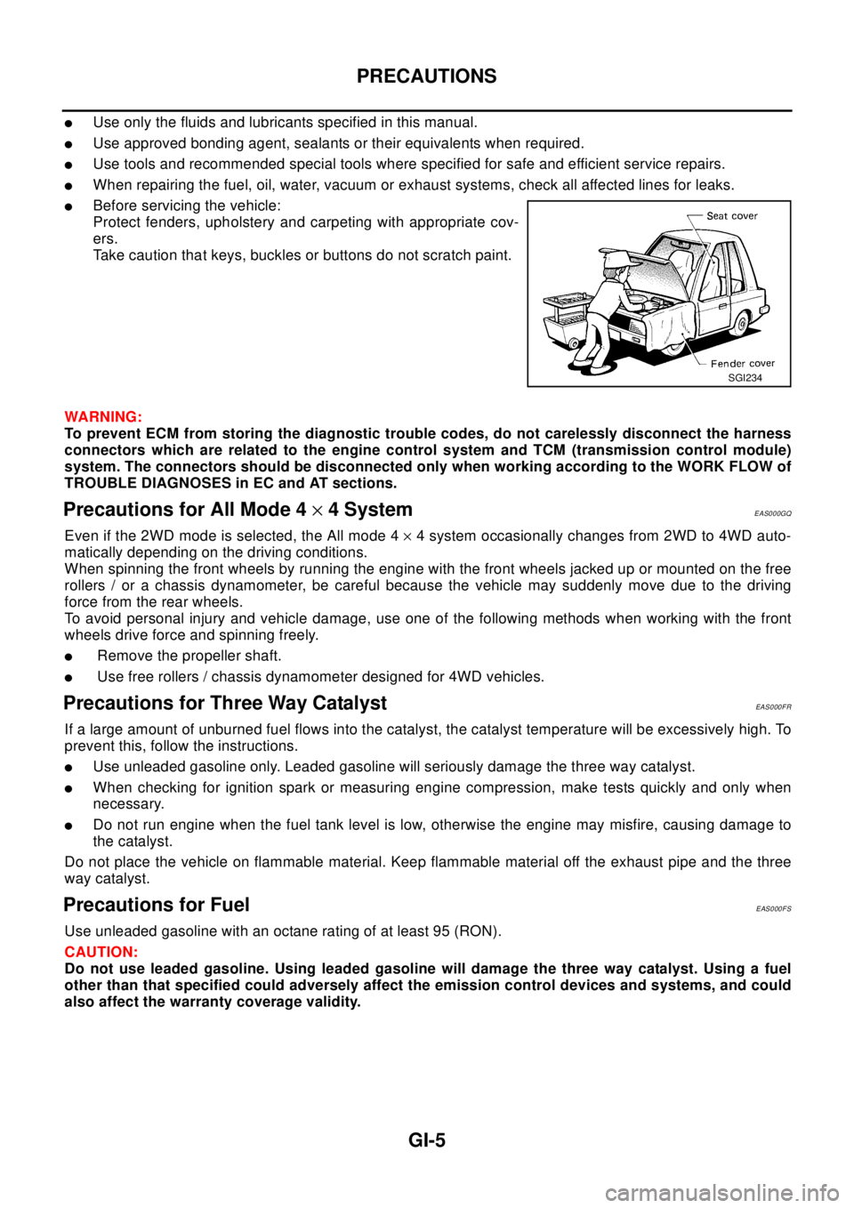
lBefore servicing the vehicle:
Protect fenders, upholstery and carpeting with appropriate cov-
ers.
Take caution that keys, buckles or buttons do not scratch paint.
WA RN ING:
To prevent ECM from storing the diagnostic trouble codes, do not carelessly disconnect the harness
connectors which are related to the engine control system and TCM (transmission control module)
system. The connectors should be disconnected only when working according to the WORK FLOW of
TROUBLE DIAGNOSES in EC and AT sections.
Precautions for All Mode 4´4 SystemEAS000GQ
Even if the 2WD mode is selected, the All mode 4´4 system occasionally changes from 2WD to 4WD auto-
matically depending on the driving conditions.
When spinning the front wheels by running the engine with the front wheels jacked up or mounted on the free
rollers / or a chassis dynamometer, be careful because the vehicle may suddenly move due to the driving
force from the rear wheels.
To avoid personal injury and vehicle damage, use one of the following methods when working with the front
wheels drive force and spinning freely.
lRemove the propeller shaft.
lUse free rollers / chassis dynamometer designed for 4WD vehicles.
Precautions for Three Way CatalystEAS000FR
If a large amount of unburned fuel flows into the catalyst, the catalyst temperature will be excessively high. To
prevent this, follow the instructions.
lUse unleaded gasoline only. Leaded gasoline will seriously damage the three way catalyst.
lWhen checking for ignition spark or measuring engine compression, make tests quickly and only when
necessary.
lDo not run engine when the fuel tank level is low, otherwise the engine may misfire, causing damage to
the catalyst.
Do not place the vehicle on flammable material. Keep flammable material off the exhaust pipe and the three
way catalyst.
Precautions for FuelEAS000FS
Use unleaded gasoline with an octane rating of at least 95 (RON).
CAUTION:
Do not use leaded gasoline. Using leaded gasoline will damage the three way catalyst. Using a fuel
other than that specified could adversely affect the emission control devices and systems, and could
also affect the warranty coverage validity.
SGI234
Page 2262 of 3066

HOW TO USE THIS MANUAL
GI-9
HOW TO USE THIS MANUALPFP:00008
DescriptionEAS000FY
This volume explains “Removal, Disassembly, Installation, Inspection and Adjustment” and “Trouble Diag-
noses”.
Te r m sEAS000FZ
lThe captionsWA RN INGandCAUTIONwarn you of steps that must be followed to prevent personal
injury and/or damage to some part of the vehicle.
WAR NIN Gindicates the possibility of personal injury if instructions are not followed.
CAUTIONindicates the possibility of component damage if instructions are not followed.
BOLD TYPED STATEMENTSexceptWA RN INGandCAUTIONgive you helpful information.
Standard value:Tolerance at inspection and adjustment.
Limit value:The maximum or minimum limit value that should not be exceeded at inspection and adjust-
ment.
UnitsEAS000G0
lTheUNITSgiven in this manual are primarily expressed as the SI UNIT (International System of Unit),
and alternatively expressed in the metric system and in the yard/pound system.
“Example”
ContentsEAS000G1
lALPHABETICAL INDEXis provided at the end of this manual so that you can rapidly find the item and
page you are searching for.
lA QUICK REFERENCE INDEX, a black tab (e.g. ) is provided on the first page. You can quickly find
the first page of each section by matching it to the section's black tab.
lTHE CONTENTSare listed on the first page of each section.
lTHE TITLEis indicated on the upper portion of each page and shows the part or system.
lTHEPAGENUMBERof each section consists of two or three letters which designate the particular sec-
tion and a number (e.g. “BR-5”).
lTHE SMALL ILLUSTRATIONSshow the important steps such as inspection, use of special tools, knacks
of work and hidden or tricky steps which are not shown in the previous large illustrations.
Assembly, inspection and adjustment procedures for the complicated units such as the automatic tran-
saxle or transmission, etc. are presented in a step-by-step format where necessary.
ComponentsEAS000G2
lTHE LARGE ILLUSTRATIONSare exploded views (See the following) and contain tightening torques,
lubrication points, section number of thePARTS CATALOG(e.g. SEC.440) and other information neces-
sary to perform repairs.Tightening torque :59 - 78 N-m (6.0 - 8.0 kg-m, 43 - 58 ft-lb)
Page 2275 of 3066

GI-22
HOW TO USE THIS MANUAL
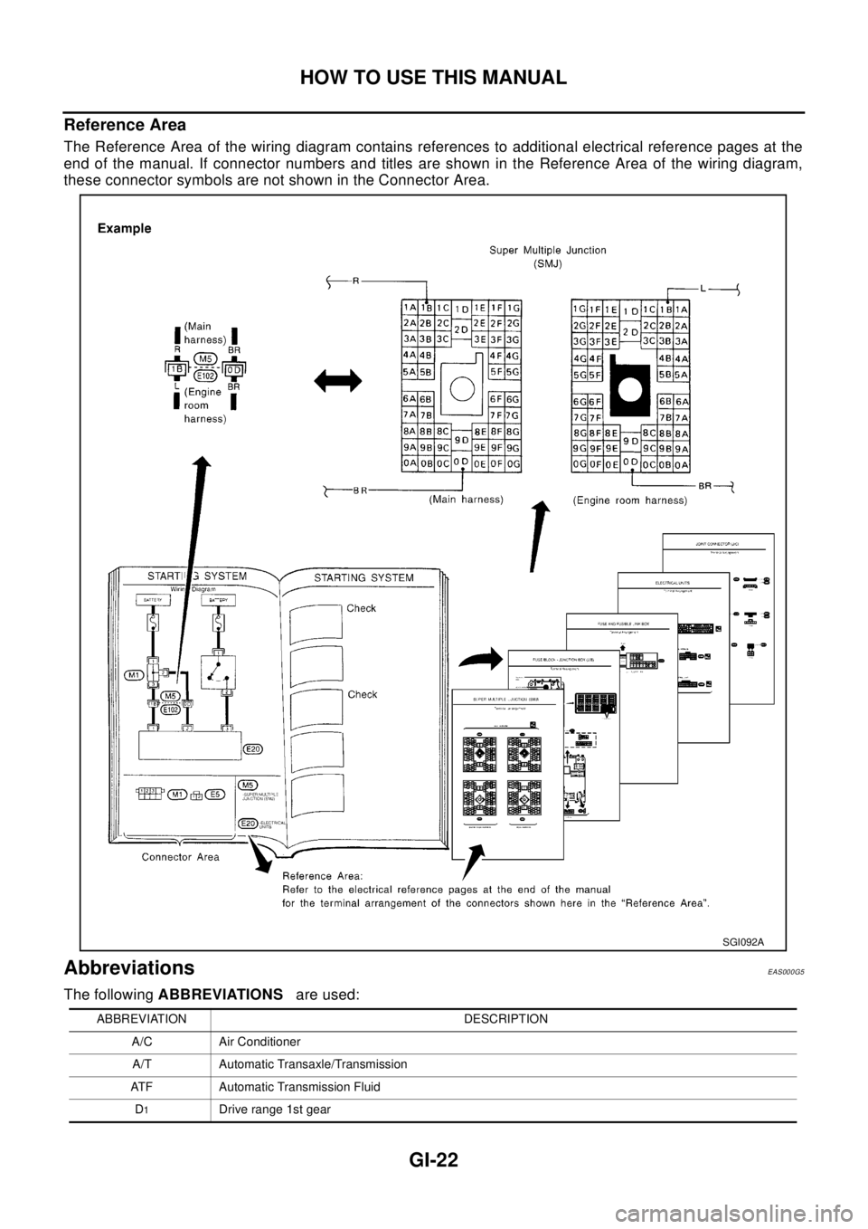
Reference Area
The Reference Area of the wiring diagram contains references to additional electrical reference pages at the
end of the manual. If connector numbers and titles are shown in the Reference Area of the wiring diagram,
these connector symbols are not shown in the Connector Area.
AbbreviationsEAS000G5
The followingABBREVIATIONSare used:
SGI092A
ABBREVIATION DESCRIPTION
A/C Air Conditioner
A/T Automatic Transaxle/Transmission
ATF Automatic Transmission Fluid
D
1Driverange1stgear
Page 2276 of 3066

HOW TO USE THIS MANUAL
GI-23
D2Drive range 2nd gear
D
3Drive range 3rd gear
D
4Drive range 4th gear
FR,RR Front,Rear
LH, RH Left-Hand, Right-Hand
M/T Manual Transaxle/Transmission
OD Overdrive
P/S Power Steering
SAE Society of Automotive Engineers, Inc.
SDS Service Data and Specifications
SST Special Service Tools
2WD 2-Wheel Drive
2
22nd range 2nd gear
2
12nd range 1st gear
1
21st range 2nd gear
1
11st range 1st gear ABBREVIATION DESCRIPTION
Page 2277 of 3066

GI-24
SERVICE INFORMATION FOR ELECTRICAL INCIDENT
SERVICE INFORMATION FOR ELECTRICAL INCIDENT
PFP:00000
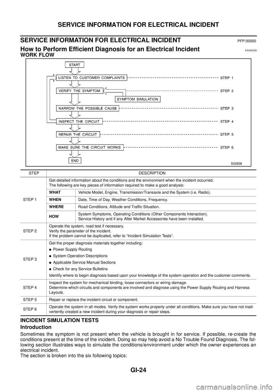
How to Perform Efficient Diagnosis for an Electrical IncidentEAS000G6
WORK FLOW
INCIDENT SIMULATION TESTS
Introduction
Sometimes the symptom is not present when the vehicle is brought in for service. If possible, re-create the
conditions present at the time of the incident. Doing so may help avoid a No Trouble Found Diagnosis. The fol-
lowing section illustrates ways to simulate the conditions/environment under which the owner experiences an
electrical incident.
The section is broken into the six following topics:
SGI838
STEP DESCRIPTION
STEP 1Get detailed information about the conditions and the environment when the incident occurred.
The following are key pieces of information required to make a good analysis:
WHATVehicle Model, Engine, Transmission/Transaxle and the System (i.e. Radio).
WHENDate, Time of Day, Weather Conditions, Frequency.
WHERERoad Conditions, Altitude and Traffic Situation.
HOWSystem Symptoms, Operating Conditions (Other Components Interaction).
Service History and if any After Market Accessories have been installed.
STEP 2Operate the system, road test if necessary.
Verify the parameter of the incident.
If the problem cannot be duplicated, refer to “Incident Simulation Tests”.
STEP 3Get the proper diagnosis materials together including:
lPower Supply Routing
lSystem Operation Descriptions
lApplicable Service Manual Sections
lCheck for any Service Bulletins
Identify where to begin diagnosis based upon your knowledge of the system operation and the customer comments.
STEP 4Inspect the system for mechanical binding, loose connectors or wiring damage.
Determine which circuits and components are involved and diagnose using the Power Supply Routing and Harness
Layouts.
STEP 5 Repair or replace the incident circuit or component.
STEP 6Operate the system in all modes. Verify the system works properly under all conditions. Make sure you have not inad-
vertently created a new incident during your diagnosis or repair steps.