Page 14 of 229
3 CHECK POWER SUPPLY
1. Stop engine.
2. Disconnect IACV-FICD solenoid valve harness connector.
SEF342V3. Start engine, then push A/C switch ON and turn fan switch to 4-speed.
4. Check voltage between terminal 1 and ground with CONSULT-II or tester.
SEC281DVoltage: Battery voltage
OK or NG
OKcGO TO 5.
NGcGO TO 4.
4 DETECT MALFUNCTIONING PART
Check the following.
Harness connectors E101, M5
Harness for open or short between IACV-FICD solenoid valve and air conditioner relay
Repair open circuit, short to ground or short to power in harness or connectors.
IACV-FICD SOLENOID VALVEKA24DE (EURO OBD)
Diagnostic Procedure (Cont'd)
EC-4010
Page 15 of 229

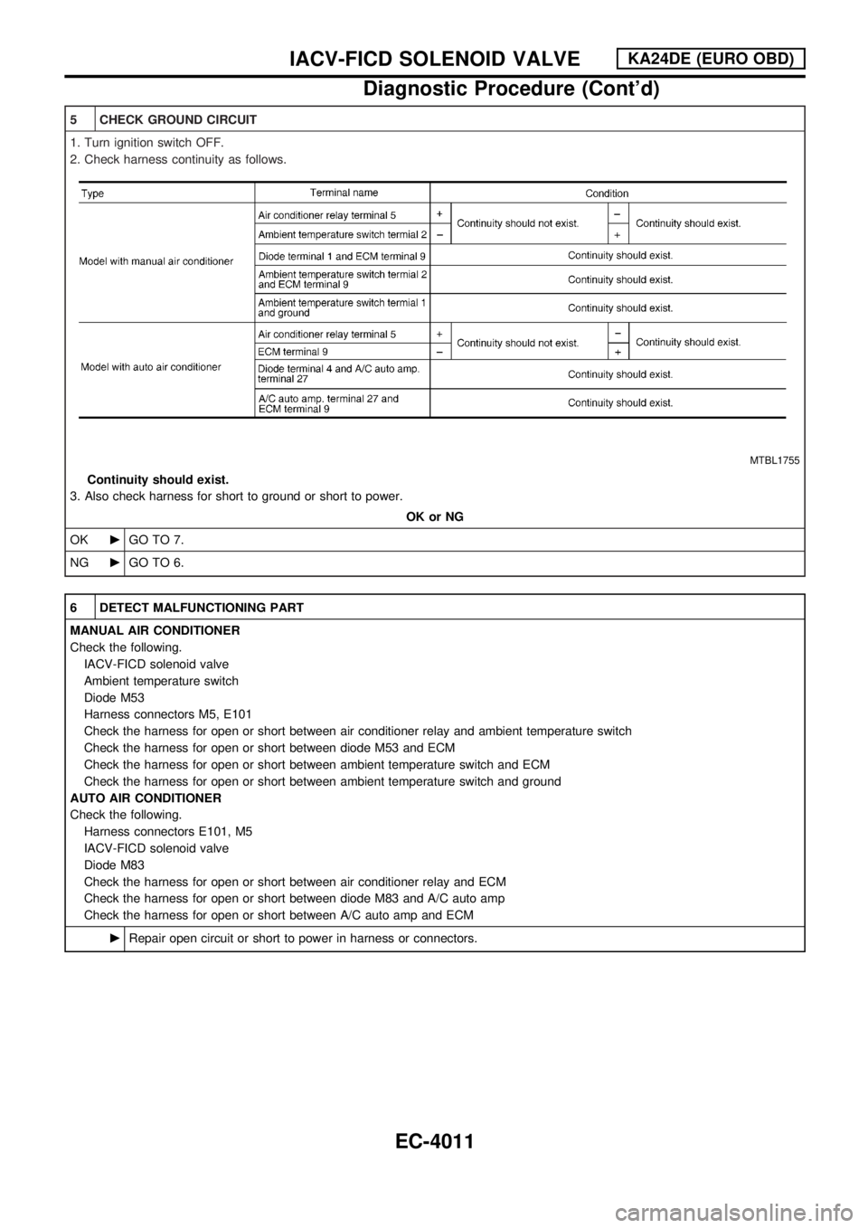
5 CHECK GROUND CIRCUIT
1. Turn ignition switch OFF.
2. Check harness continuity as follows.
MTBL1755
Continuity should exist.
3. Also check harness for short to ground or short to power.
OK or NG
OKcGO TO 7.
NGcGO TO 6.
6 DETECT MALFUNCTIONING PART
MANUAL AIR CONDITIONER
Check the following.
IACV-FICD solenoid valve
Ambient temperature switch
Diode M53
Harness connectors M5, E101
Check the harness for open or short between air conditioner relay and ambient temperature switch
Check the harness for open or short between diode M53 and ECM
Check the harness for open or short between ambient temperature switch and ECM
Check the harness for open or short between ambient temperature switch and ground
AUTO AIR CONDITIONER
Check the following.
Harness connectors E101, M5
IACV-FICD solenoid valve
Diode M83
Check the harness for open or short between air conditioner relay and ECM
Check the harness for open or short between diode M83 and A/C auto amp
Check the harness for open or short between A/C auto amp and ECM
cRepair open circuit or short to power in harness or connectors.
IACV-FICD SOLENOID VALVEKA24DE (EURO OBD)
Diagnostic Procedure (Cont'd)
EC-4011
Page 105 of 229

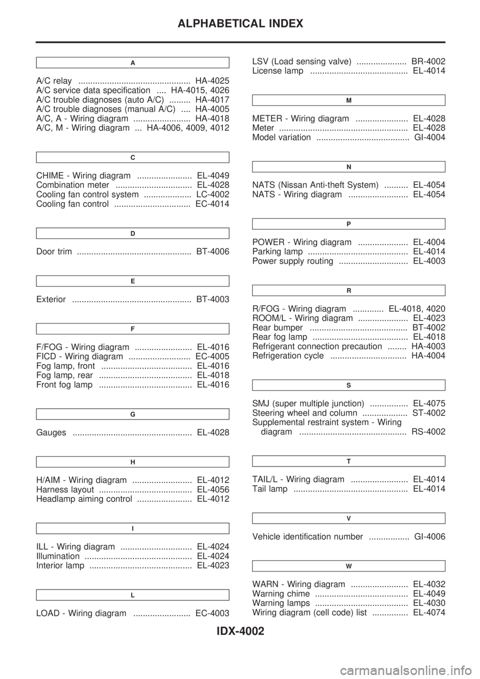
A
A/C relay ............................................... HA-4025
A/C service data specification .... HA-4015, 4026
A/C trouble diagnoses (auto A/C) ......... HA-4017
A/C trouble diagnoses (manual A/C) .... HA-4005
A/C, A - Wiring diagram ........................ HA-4018
A/C, M - Wiring diagram ... HA-4006, 4009, 4012
C
CHIME - Wiring diagram ....................... EL-4049
Combination meter ................................ EL-4028
Cooling fan control system .................... LC-4002
Cooling fan control ................................ EC-4014
D
Door trim ................................................ BT-4006
E
Exterior .................................................. BT-4003
F
F/FOG - Wiring diagram ........................ EL-4016
FICD - Wiring diagram .......................... EC-4005
Fog lamp, front ...................................... EL-4016
Fog lamp, rear ....................................... EL-4018
Front fog lamp ....................................... EL-4016
G
Gauges .................................................. EL-4028
H
H/AIM - Wiring diagram ......................... EL-4012
Harness layout ....................................... EL-4056
Headlamp aiming control ....................... EL-4012
I
ILL - Wiring diagram .............................. EL-4024
Illumination ............................................. EL-4024
Interior lamp ........................................... EL-4023
L
LOAD - Wiring diagram ........................ EC-4003LSV (Load sensing valve) ..................... BR-4002
License lamp ......................................... EL-4014
M
METER - Wiring diagram ...................... EL-4028
Meter ...................................................... EL-4028
Model variation ....................................... GI-4004
N
NATS (Nissan Anti-theft System) .......... EL-4054
NATS - Wiring diagram ......................... EL-4054
P
POWER - Wiring diagram ..................... EL-4004
Parking lamp .......................................... EL-4014
Power supply routing ............................. EL-4003
R
R/FOG - Wiring diagram ............. EL-4018, 4020
ROOM/L - Wiring diagram ..................... EL-4023
Rear bumper ......................................... BT-4002
Rear fog lamp ........................................ EL-4018
Refrigerant connection precaution ........ HA-4003
Refrigeration cycle ................................ HA-4004
S
SMJ (super multiple junction) ................ EL-4075
Steering wheel and column ................... ST-4002
Supplemental restraint system - Wiring
diagram ............................................. RS-4002
T
TAIL/L - Wiring diagram ........................ EL-4014
Tail lamp ................................................ EL-4014
V
Vehicle identification number ................. GI-4006
W
WARN - Wiring diagram ........................ EL-4032
Warning chime ....................................... EL-4049
Warning lamps ....................................... EL-4030
Wiring diagram (cell code) list ............... EL-4074
ALPHABETICAL INDEX
IDX-4002
Page 129 of 229

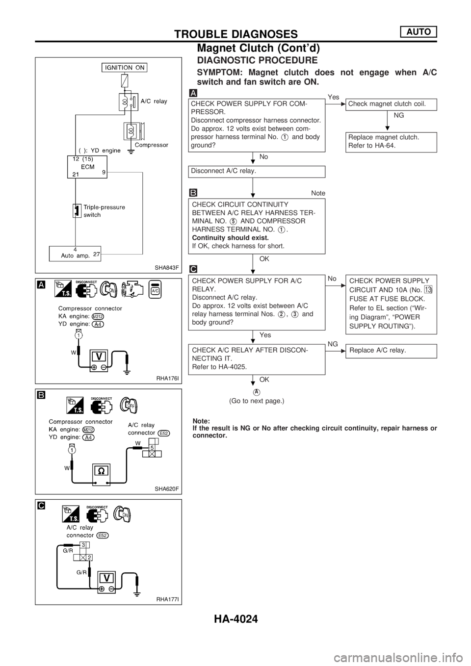
DIAGNOSTIC PROCEDURE
SYMPTOM: Magnet clutch does not engage when A/C
switch and fan switch are ON.
CHECK POWER SUPPLY FOR COM-
PRESSOR.
Disconnect compressor harness connector.
Do approx. 12 volts exist between com-
pressor harness terminal No.
V1and body
ground?
No
cYes
Check magnet clutch coil.
NG
Replace magnet clutch.
Refer to HA-64.
Disconnect A/C relay.
Note
CHECK CIRCUIT CONTINUITY
BETWEEN A/C RELAY HARNESS TER-
MINAL NO.
V5AND COMPRESSOR
HARNESS TERMINAL NO.
V1.
Continuity should exist.
If OK, check harness for short.
OK
CHECK POWER SUPPLY FOR A/C
RELAY.
Disconnect A/C relay.
Do approx. 12 volts exist between A/C
relay harness terminal Nos.
V2,V3and
body ground?
Yes
cNo
CHECK POWER SUPPLY
CIRCUIT AND 10A (No.
13)
FUSE AT FUSE BLOCK.
Refer to EL section (ªWir-
ing Diagramº, ªPOWER
SUPPLY ROUTINGº).
CHECK A/C RELAY AFTER DISCON-
NECTING IT.
Refer to HA-4025.
OK
cNG
Replace A/C relay.
VA
(Go to next page.)
Note:
If the result is NG or No after checking circuit continuity, repair harness or
connector.
SHA843F
RHA176I
SHA620F
RHA177I
.
.
.
.
.
.
TROUBLE DIAGNOSESAUTO
Magnet Clutch (Cont'd)
HA-4024
Page 130 of 229

VA
NoteNote
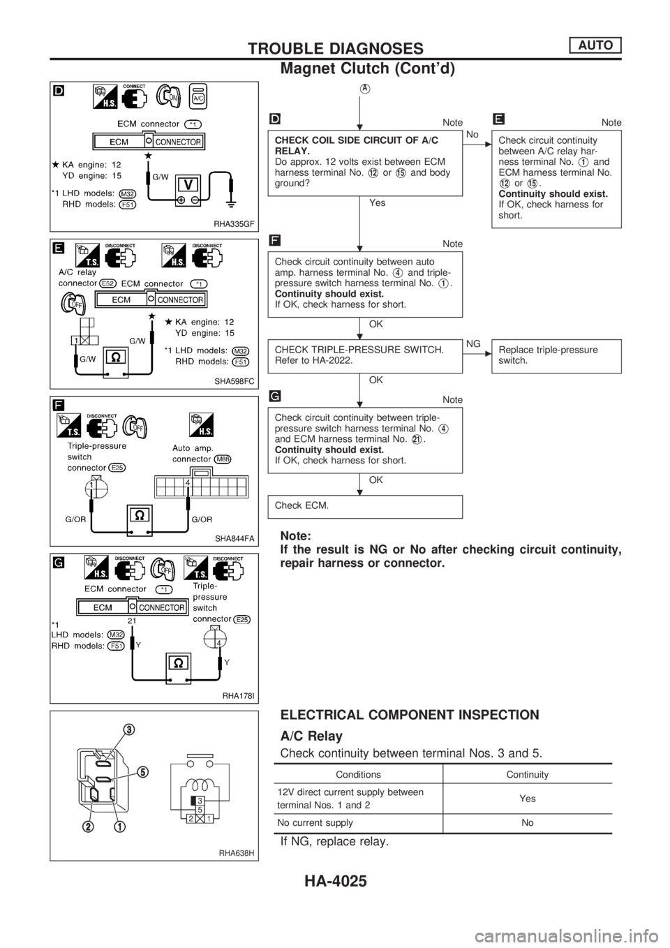
CHECK COIL SIDE CIRCUIT OF A/C
RELAY.
Do approx. 12 volts exist between ECM
harness terminal No.
V12orV15and body
ground?
Yes
cNo
Check circuit continuity
between A/C relay har-
ness terminal No.
V1and
ECM harness terminal No.
V12orV15.
Continuity should exist.
If OK, check harness for
short.
Note
Check circuit continuity between auto
amp. harness terminal No.
V4and triple-
pressure switch harness terminal No.
V1.
Continuity should exist.
If OK, check harness for short.
OK
CHECK TRIPLE-PRESSURE SWITCH.
Refer to HA-2022.
OK
cNG
Replace triple-pressure
switch.
Note
Check circuit continuity between triple-
pressure switch harness terminal No.
V4and ECM harness terminal No.V21.
Continuity should exist.
If OK, check harness for short.
OK
Check ECM.
Note:
If the result is NG or No after checking circuit continuity,
repair harness or connector.
ELECTRICAL COMPONENT INSPECTION
A/C Relay
Check continuity between terminal Nos. 3 and 5.
Conditions Continuity
12V direct current supply between
terminal Nos. 1 and 2Yes
No current supply No
If NG, replace relay.
RHA335GF
SHA598FC
SHA844FA
RHA178I
RHA638H
.
.
. .
.
.
TROUBLE DIAGNOSESAUTO
Magnet Clutch (Cont'd)
HA-4025