2003 NISSAN PICK-UP cooling
[x] Cancel search: coolingPage 1 of 229
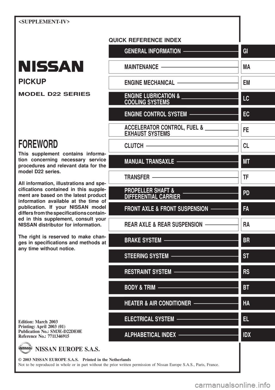
GENERAL INFORMATIONGI
MAINTENANCEMA
ENGINE MECHANICALEM
ENGINE LUBRICATION &
COOLING SYSTEMSLC
ENGINE CONTROL SYSTEMEC
ACCELERATOR CONTROL, FUEL &
EXHAUST SYSTEMSFE
CLUTCHCL
MANUAL TRANSAXLEMT
TRANSFERTF
PROPELLER SHAFT &
DIFFERENTIAL CARRIERPD
FRONT AXLE & FRONT SUSPENSIONFA
REAR AXLE & REAR SUSPENSIONRA
BRAKE SYSTEMBR
STEERING SYSTEMST
RESTRAINT SYSTEMRS
BODY & TRIMBT
HEATER & AIR CONDITIONERHA
ELECTRICAL SYSTEMEL
ALPHABETICAL INDEXIDX
PICKUP
MODEL D22 SERIES
FOREWORD
This supplement contains informa-
tion concerning necessary service
procedures and relevant data for the
model D22 series.
All information, illustrations and spe-
ci®cations contained in this supple-
ment are based on the latest product
information available at the time of
publication. If your NISSAN model
differs from the speci®cations contain-
ed in this supplement, consult your
NISSAN distributor for information.
The right is reserved to make chan-
ges in speci®cations and methods at
any time without notice.
Edition: March 2003
Printing: April 2003 (01)
Publication No.: SM3E-D22DE0E
Reference No.: 7711346915
NISSAN EUROPE S.A.S.
2003 NISSAN EUROPE S.A.S. Printed in the Netherlands
Not to be reproduced in whole or in part without the prior written permission of Nissan Europe S.A.S., Paris, France.
QUICK REFERENCE INDEX
Page 103 of 229
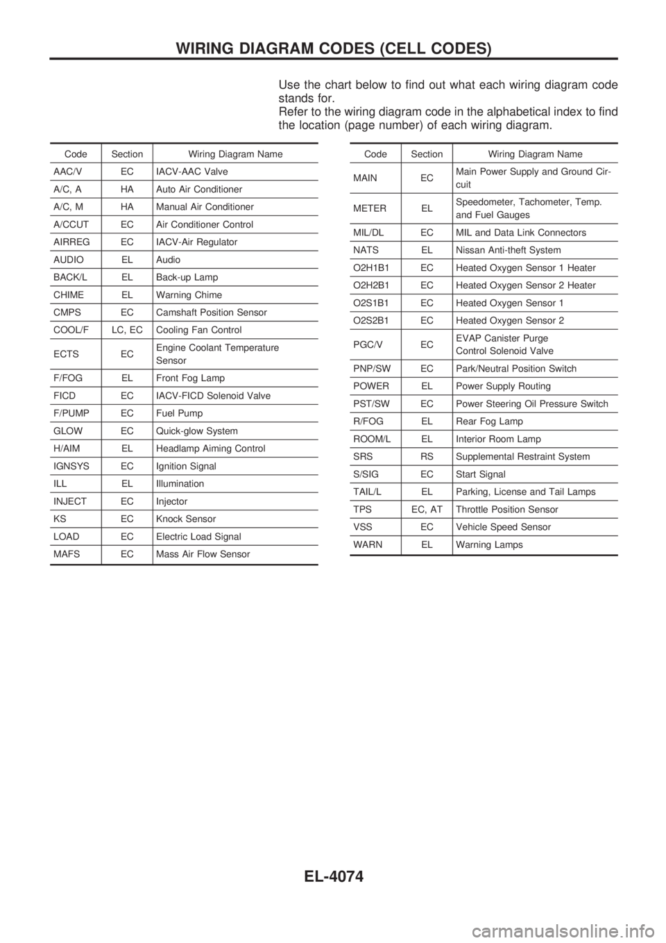
Use the chart below to find out what each wiring diagram code
stands for.
Refer to the wiring diagram code in the alphabetical index to find
the location (page number) of each wiring diagram.
Code Section Wiring Diagram Name
AAC/V EC IACV-AAC Valve
A/C, A HA Auto Air Conditioner
A/C, M HA Manual Air Conditioner
A/CCUT EC Air Conditioner Control
AIRREG EC IACV-Air Regulator
AUDIO EL Audio
BACK/L EL Back-up Lamp
CHIME EL Warning Chime
CMPS EC Camshaft Position Sensor
COOL/F LC, EC Cooling Fan Control
ECTS ECEngine Coolant Temperature
Sensor
F/FOG EL Front Fog Lamp
FICD EC IACV-FICD Solenoid Valve
F/PUMP EC Fuel Pump
GLOW EC Quick-glow System
H/AIM EL Headlamp Aiming Control
IGNSYS EC Ignition Signal
ILL EL Illumination
INJECT EC Injector
KS EC Knock Sensor
LOAD EC Electric Load Signal
MAFS EC Mass Air Flow SensorCode Section Wiring Diagram Name
MAIN ECMain Power Supply and Ground Cir-
cuit
METER ELSpeedometer, Tachometer, Temp.
and Fuel Gauges
MIL/DL EC MIL and Data Link Connectors
NATS EL Nissan Anti-theft System
O2H1B1 EC Heated Oxygen Sensor 1 Heater
O2H2B1 EC Heated Oxygen Sensor 2 Heater
O2S1B1 EC Heated Oxygen Sensor 1
O2S2B1 EC Heated Oxygen Sensor 2
PGC/V ECEVAP Canister Purge
Control Solenoid Valve
PNP/SW EC Park/Neutral Position Switch
POWER EL Power Supply Routing
PST/SW EC Power Steering Oil Pressure Switch
R/FOG EL Rear Fog Lamp
ROOM/L EL Interior Room Lamp
SRS RS Supplemental Restraint System
S/SIG EC Start Signal
TAIL/L EL Parking, License and Tail Lamps
TPS EC, AT Throttle Position Sensor
VSS EC Vehicle Speed Sensor
WARN EL Warning Lamps
WIRING DIAGRAM CODES (CELL CODES)
EL-4074
Page 105 of 229
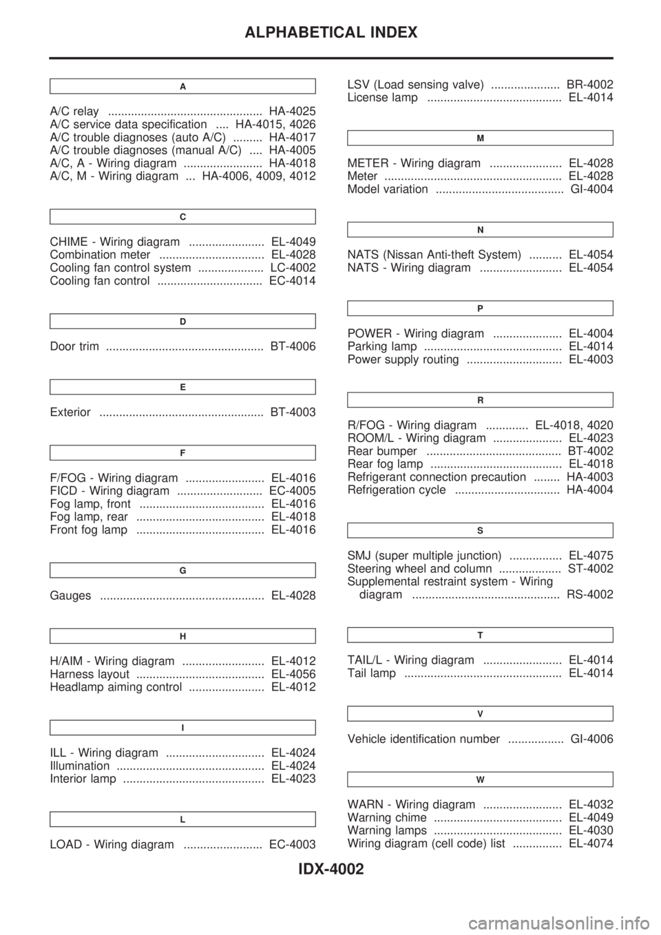
A
A/C relay ............................................... HA-4025
A/C service data specification .... HA-4015, 4026
A/C trouble diagnoses (auto A/C) ......... HA-4017
A/C trouble diagnoses (manual A/C) .... HA-4005
A/C, A - Wiring diagram ........................ HA-4018
A/C, M - Wiring diagram ... HA-4006, 4009, 4012
C
CHIME - Wiring diagram ....................... EL-4049
Combination meter ................................ EL-4028
Cooling fan control system .................... LC-4002
Cooling fan control ................................ EC-4014
D
Door trim ................................................ BT-4006
E
Exterior .................................................. BT-4003
F
F/FOG - Wiring diagram ........................ EL-4016
FICD - Wiring diagram .......................... EC-4005
Fog lamp, front ...................................... EL-4016
Fog lamp, rear ....................................... EL-4018
Front fog lamp ....................................... EL-4016
G
Gauges .................................................. EL-4028
H
H/AIM - Wiring diagram ......................... EL-4012
Harness layout ....................................... EL-4056
Headlamp aiming control ....................... EL-4012
I
ILL - Wiring diagram .............................. EL-4024
Illumination ............................................. EL-4024
Interior lamp ........................................... EL-4023
L
LOAD - Wiring diagram ........................ EC-4003LSV (Load sensing valve) ..................... BR-4002
License lamp ......................................... EL-4014
M
METER - Wiring diagram ...................... EL-4028
Meter ...................................................... EL-4028
Model variation ....................................... GI-4004
N
NATS (Nissan Anti-theft System) .......... EL-4054
NATS - Wiring diagram ......................... EL-4054
P
POWER - Wiring diagram ..................... EL-4004
Parking lamp .......................................... EL-4014
Power supply routing ............................. EL-4003
R
R/FOG - Wiring diagram ............. EL-4018, 4020
ROOM/L - Wiring diagram ..................... EL-4023
Rear bumper ......................................... BT-4002
Rear fog lamp ........................................ EL-4018
Refrigerant connection precaution ........ HA-4003
Refrigeration cycle ................................ HA-4004
S
SMJ (super multiple junction) ................ EL-4075
Steering wheel and column ................... ST-4002
Supplemental restraint system - Wiring
diagram ............................................. RS-4002
T
TAIL/L - Wiring diagram ........................ EL-4014
Tail lamp ................................................ EL-4014
V
Vehicle identification number ................. GI-4006
W
WARN - Wiring diagram ........................ EL-4032
Warning chime ....................................... EL-4049
Warning lamps ....................................... EL-4030
Wiring diagram (cell code) list ............... EL-4074
ALPHABETICAL INDEX
IDX-4002
Page 108 of 229
Precautions for Refrigerant Connection
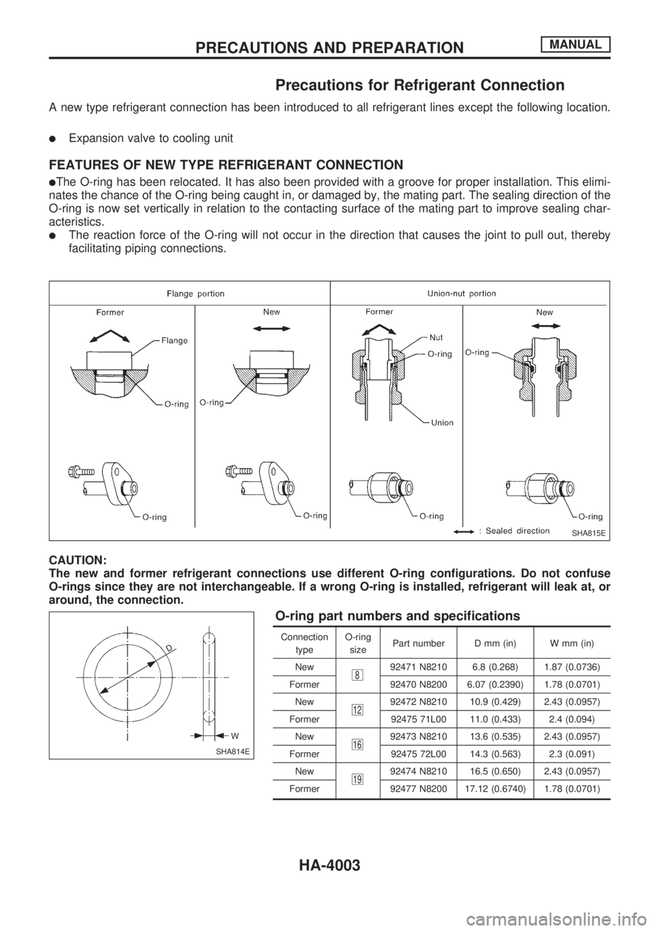
A new type refrigerant connection has been introduced to all refrigerant lines except the following location.
lExpansion valve to cooling unit
FEATURES OF NEW TYPE REFRIGERANT CONNECTION
lThe O-ring has been relocated. It has also been provided with a groove for proper installation. This elimi-
nates the chance of the O-ring being caught in, or damaged by, the mating part. The sealing direction of the
O-ring is now set vertically in relation to the contacting surface of the mating part to improve sealing char-
acteristics.
lThe reaction force of the O-ring will not occur in the direction that causes the joint to pull out, thereby
facilitating piping connections.
CAUTION:
The new and former refrigerant connections use different O-ring configurations. Do not confuse
O-rings since they are not interchangeable. If a wrong O-ring is installed, refrigerant will leak at, or
around, the connection.
O-ring part numbers and specifications
Connection
typeO-ring
sizePart number D mm (in) W mm (in)
New
892471 N8210 6.8 (0.268) 1.87 (0.0736)
Former 92470 N8200 6.07 (0.2390) 1.78 (0.0701)
New
1292472 N8210 10.9 (0.429) 2.43 (0.0957)
Former 92475 71L00 11.0 (0.433) 2.4 (0.094)
New
1692473 N8210 13.6 (0.535) 2.43 (0.0957)
Former 92475 72L00 14.3 (0.563) 2.3 (0.091)
New
1992474 N8210 16.5 (0.650) 2.43 (0.0957)
Former 92477 N8200 17.12 (0.6740) 1.78 (0.0701)
SHA815E
SHA814E
PRECAUTIONS AND PREPARATIONMANUAL
HA-4003
Page 153 of 229
ENGINE LUBRICATION &
COOLING SYSTEMS
SECTION
LC
MODIFICATION NOTICE:
lWiring diagrams have been changed for KA24DE models.
CONTENTS
ENGINE ROOM FAN MOTOR ELECTRICAL
CIRCUIT...............................................................4002
Wiring Diagram ................................................ 4002ENGINE ROOM FAN MOTOR............................ 4003
Cooling Fan (Motor driven) .............................. 4003
LC
Page 155 of 229

Cooling Fan (Motor driven)
SLC507BA
ENGINE ROOM FAN MOTORKA24DE
LC-4003
Page 229 of 229
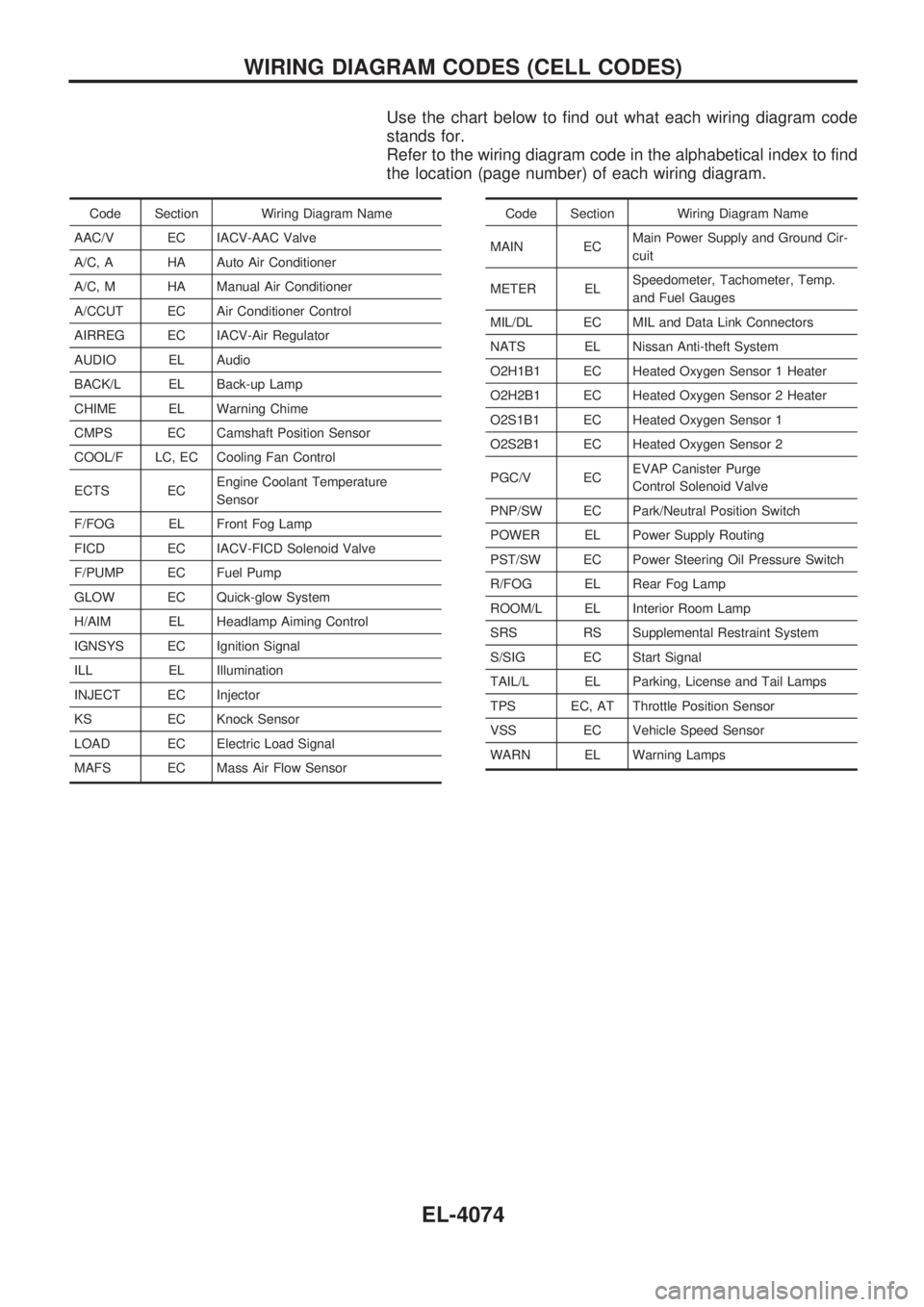
Use the chart below to find out what each wiring diagram code
stands for.
Refer to the wiring diagram code in the alphabetical index to find
the location (page number) of each wiring diagram.
Code Section Wiring Diagram Name
AAC/V EC IACV-AAC Valve
A/C, A HA Auto Air Conditioner
A/C, M HA Manual Air Conditioner
A/CCUT EC Air Conditioner Control
AIRREG EC IACV-Air Regulator
AUDIO EL Audio
BACK/L EL Back-up Lamp
CHIME EL Warning Chime
CMPS EC Camshaft Position Sensor
COOL/F LC, EC Cooling Fan Control
ECTS ECEngine Coolant Temperature
Sensor
F/FOG EL Front Fog Lamp
FICD EC IACV-FICD Solenoid Valve
F/PUMP EC Fuel Pump
GLOW EC Quick-glow System
H/AIM EL Headlamp Aiming Control
IGNSYS EC Ignition Signal
ILL EL Illumination
INJECT EC Injector
KS EC Knock Sensor
LOAD EC Electric Load Signal
MAFS EC Mass Air Flow SensorCode Section Wiring Diagram Name
MAIN ECMain Power Supply and Ground Cir-
cuit
METER ELSpeedometer, Tachometer, Temp.
and Fuel Gauges
MIL/DL EC MIL and Data Link Connectors
NATS EL Nissan Anti-theft System
O2H1B1 EC Heated Oxygen Sensor 1 Heater
O2H2B1 EC Heated Oxygen Sensor 2 Heater
O2S1B1 EC Heated Oxygen Sensor 1
O2S2B1 EC Heated Oxygen Sensor 2
PGC/V ECEVAP Canister Purge
Control Solenoid Valve
PNP/SW EC Park/Neutral Position Switch
POWER EL Power Supply Routing
PST/SW EC Power Steering Oil Pressure Switch
R/FOG EL Rear Fog Lamp
ROOM/L EL Interior Room Lamp
SRS RS Supplemental Restraint System
S/SIG EC Start Signal
TAIL/L EL Parking, License and Tail Lamps
TPS EC, AT Throttle Position Sensor
VSS EC Vehicle Speed Sensor
WARN EL Warning Lamps
WIRING DIAGRAM CODES (CELL CODES)
EL-4074