Page 82 of 229
GEL683A
AUDIO
Wiring Diagram Ð AUDIO Ð/RHD Models
(Cont'd)
EL-4053
Page 83 of 229
Wiring Diagram Ð NATS Ð/LHD Models
GEL684A
NATS (Nissan Anti-Theft System)
EL-4054
Page 84 of 229
Wiring Diagram Ð NATS Ð/RHD Models
GEL685A
NATS (Nissan Anti-Theft System)
EL-4055
Page 103 of 229

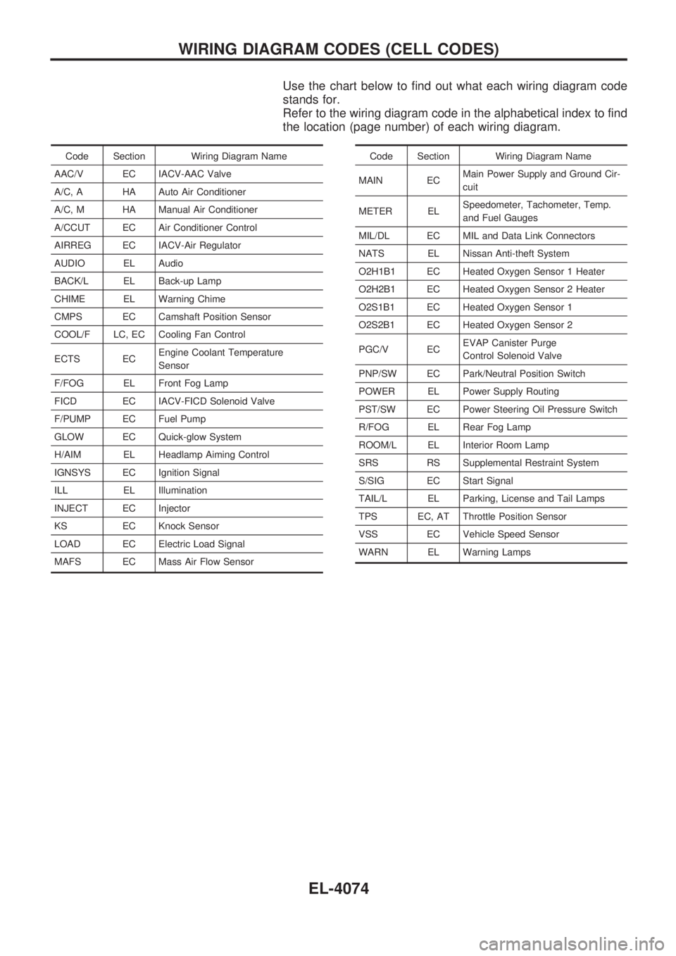
Use the chart below to find out what each wiring diagram code
stands for.
Refer to the wiring diagram code in the alphabetical index to find
the location (page number) of each wiring diagram.
Code Section Wiring Diagram Name
AAC/V EC IACV-AAC Valve
A/C, A HA Auto Air Conditioner
A/C, M HA Manual Air Conditioner
A/CCUT EC Air Conditioner Control
AIRREG EC IACV-Air Regulator
AUDIO EL Audio
BACK/L EL Back-up Lamp
CHIME EL Warning Chime
CMPS EC Camshaft Position Sensor
COOL/F LC, EC Cooling Fan Control
ECTS ECEngine Coolant Temperature
Sensor
F/FOG EL Front Fog Lamp
FICD EC IACV-FICD Solenoid Valve
F/PUMP EC Fuel Pump
GLOW EC Quick-glow System
H/AIM EL Headlamp Aiming Control
IGNSYS EC Ignition Signal
ILL EL Illumination
INJECT EC Injector
KS EC Knock Sensor
LOAD EC Electric Load Signal
MAFS EC Mass Air Flow SensorCode Section Wiring Diagram Name
MAIN ECMain Power Supply and Ground Cir-
cuit
METER ELSpeedometer, Tachometer, Temp.
and Fuel Gauges
MIL/DL EC MIL and Data Link Connectors
NATS EL Nissan Anti-theft System
O2H1B1 EC Heated Oxygen Sensor 1 Heater
O2H2B1 EC Heated Oxygen Sensor 2 Heater
O2S1B1 EC Heated Oxygen Sensor 1
O2S2B1 EC Heated Oxygen Sensor 2
PGC/V ECEVAP Canister Purge
Control Solenoid Valve
PNP/SW EC Park/Neutral Position Switch
POWER EL Power Supply Routing
PST/SW EC Power Steering Oil Pressure Switch
R/FOG EL Rear Fog Lamp
ROOM/L EL Interior Room Lamp
SRS RS Supplemental Restraint System
S/SIG EC Start Signal
TAIL/L EL Parking, License and Tail Lamps
TPS EC, AT Throttle Position Sensor
VSS EC Vehicle Speed Sensor
WARN EL Warning Lamps
WIRING DIAGRAM CODES (CELL CODES)
EL-4074
Page 105 of 229

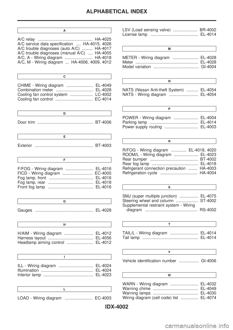
A
A/C relay ............................................... HA-4025
A/C service data specification .... HA-4015, 4026
A/C trouble diagnoses (auto A/C) ......... HA-4017
A/C trouble diagnoses (manual A/C) .... HA-4005
A/C, A - Wiring diagram ........................ HA-4018
A/C, M - Wiring diagram ... HA-4006, 4009, 4012
C
CHIME - Wiring diagram ....................... EL-4049
Combination meter ................................ EL-4028
Cooling fan control system .................... LC-4002
Cooling fan control ................................ EC-4014
D
Door trim ................................................ BT-4006
E
Exterior .................................................. BT-4003
F
F/FOG - Wiring diagram ........................ EL-4016
FICD - Wiring diagram .......................... EC-4005
Fog lamp, front ...................................... EL-4016
Fog lamp, rear ....................................... EL-4018
Front fog lamp ....................................... EL-4016
G
Gauges .................................................. EL-4028
H
H/AIM - Wiring diagram ......................... EL-4012
Harness layout ....................................... EL-4056
Headlamp aiming control ....................... EL-4012
I
ILL - Wiring diagram .............................. EL-4024
Illumination ............................................. EL-4024
Interior lamp ........................................... EL-4023
L
LOAD - Wiring diagram ........................ EC-4003LSV (Load sensing valve) ..................... BR-4002
License lamp ......................................... EL-4014
M
METER - Wiring diagram ...................... EL-4028
Meter ...................................................... EL-4028
Model variation ....................................... GI-4004
N
NATS (Nissan Anti-theft System) .......... EL-4054
NATS - Wiring diagram ......................... EL-4054
P
POWER - Wiring diagram ..................... EL-4004
Parking lamp .......................................... EL-4014
Power supply routing ............................. EL-4003
R
R/FOG - Wiring diagram ............. EL-4018, 4020
ROOM/L - Wiring diagram ..................... EL-4023
Rear bumper ......................................... BT-4002
Rear fog lamp ........................................ EL-4018
Refrigerant connection precaution ........ HA-4003
Refrigeration cycle ................................ HA-4004
S
SMJ (super multiple junction) ................ EL-4075
Steering wheel and column ................... ST-4002
Supplemental restraint system - Wiring
diagram ............................................. RS-4002
T
TAIL/L - Wiring diagram ........................ EL-4014
Tail lamp ................................................ EL-4014
V
Vehicle identification number ................. GI-4006
W
WARN - Wiring diagram ........................ EL-4032
Warning chime ....................................... EL-4049
Warning lamps ....................................... EL-4030
Wiring diagram (cell code) list ............... EL-4074
ALPHABETICAL INDEX
IDX-4002
Page 106 of 229

HEATER &
AIR CONDITIONER
SECTION
HA
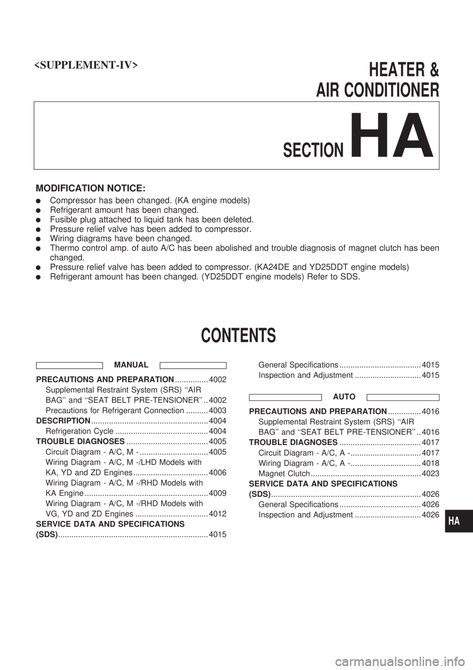
MODIFICATION NOTICE:
lCompressor has been changed. (KA engine models)
lRefrigerant amount has been changed.
lFusible plug attached to liquid tank has been deleted.
lPressure relief valve has been added to compressor.
lWiring diagrams have been changed.
lThermo control amp. of auto A/C has been abolished and trouble diagnosis of magnet clutch has been
changed.
lPressure relief valve has been added to compressor. (KA24DE and YD25DDT engine models)
lRefrigerant amount has been changed. (YD25DDT engine models) Refer to SDS.
CONTENTS
MANUAL
PRECAUTIONS AND PREPARATION............... 4002
Supplemental Restraint System (SRS) ``AIR
BAG'' and ``SEAT BELT PRE-TENSIONER'' .. 4002
Precautions for Refrigerant Connection .......... 4003
DESCRIPTION..................................................... 4004
Refrigeration Cycle .......................................... 4004
TROUBLE DIAGNOSES..................................... 4005
Circuit Diagram - A/C, M - ............................... 4005
Wiring Diagram - A/C, M -/LHD Models with
KA, YD and ZD Engines .................................. 4006
Wiring Diagram - A/C, M -/RHD Models with
KA Engine ........................................................ 4009
Wiring Diagram - A/C, M -/RHD Models with
VG, YD and ZD Engines ................................. 4012
SERVICE DATA AND SPECIFICATIONS
(SDS).................................................................... 4015General Specifications ..................................... 4015
Inspection and Adjustment .............................. 4015
AUTO
PRECAUTIONS AND PREPARATION............... 4016
Supplemental Restraint System (SRS) ``AIR
BAG'' and ``SEAT BELT PRE-TENSIONER'' .. 4016
TROUBLE DIAGNOSES..................................... 4017
Circuit Diagram - A/C, A -................................ 4017
Wiring Diagram - A/C, A -................................ 4018
Magnet Clutch .................................................. 4023
SERVICE DATA AND SPECIFICATIONS
(SDS).................................................................... 4026
General Specifications ..................................... 4026
Inspection and Adjustment .............................. 4026
HA
Page 107 of 229

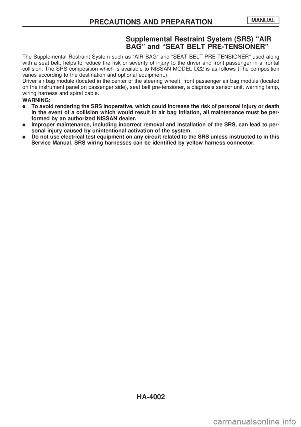
Supplemental Restraint System (SRS) ªAIR
BAGº and ªSEAT BELT PRE-TENSIONERº
The Supplemental Restraint System such as ªAIR BAGº and ªSEAT BELT PRE-TENSIONERº used along
with a seat belt, helps to reduce the risk or severity of injury to the driver and front passenger in a frontal
collision. The SRS composition which is available to NISSAN MODEL D22 is as follows (The composition
varies according to the destination and optional equipment.):
Driver air bag module (located in the center of the steering wheel), front passenger air bag module (located
on the instrument panel on passenger side), seat belt pre-tensioner, a diagnosis sensor unit, warning lamp,
wiring harness and spiral cable.
WARNING:
lTo avoid rendering the SRS inoperative, which could increase the risk of personal injury or death
in the event of a collision which would result in air bag inflation, all maintenance must be per-
formed by an authorized NISSAN dealer.
lImproper maintenance, including incorrect removal and installation of the SRS, can lead to per-
sonal injury caused by unintentional activation of the system.
lDo not use electrical test equipment on any circuit related to the SRS unless instructed to in this
Service Manual. SRS wiring harnesses can be identified by yellow harness connector.
PRECAUTIONS AND PREPARATIONMANUAL
HA-4002
Page 111 of 229
Wiring Diagram Ð A/C, M Ð/LHD Models
with KA, YD and ZD Engines
GHA056A
TROUBLE DIAGNOSESMANUAL
HA-4006