2003 NISSAN ALMERA N16 low oil pressure
[x] Cancel search: low oil pressurePage 1995 of 3189
REFRIGERATION SYSTEM
ATC-15
C
D
E
F
G
H
I
K
L
MA
B
AT C
REFRIGERATION SYSTEMPFP:KA990
Refrigerant CycleEJS001Z0
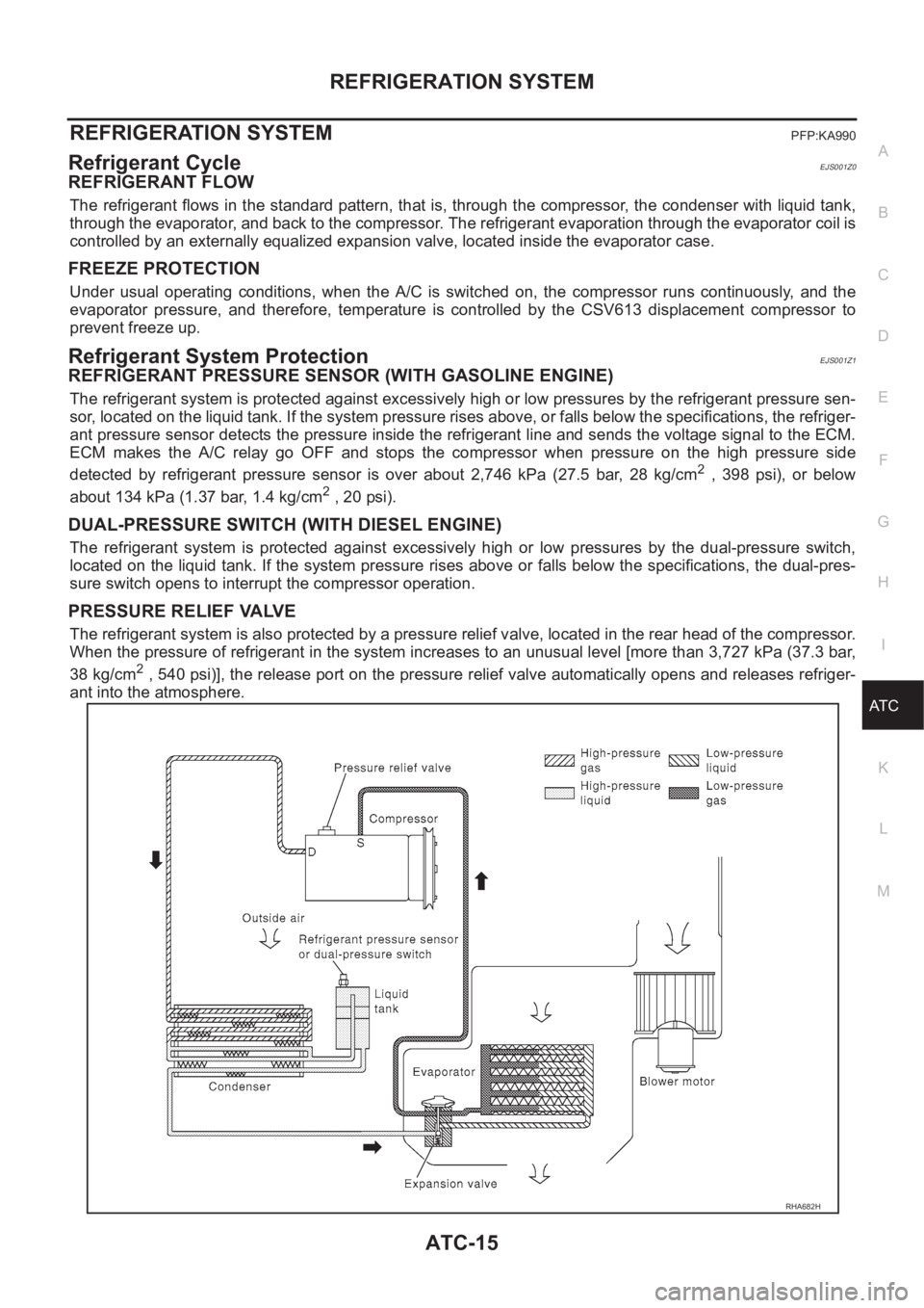
REFRIGERANT FLOW
The refrigerant flows in the standard pattern, that is, through the compressor, the condenser with liquid tank,
through the evaporator, and back to the compressor. The refrigerant evaporation through the evaporator coil is
controlled by an externally equalized expansion valve, located inside the evaporator case.
FREEZE PROTECTION
Under usual operating conditions, when the A/C is switched on, the compressor runs continuously, and the
evaporator pressure, and therefore, temperature is controlled by the CSV613 displacement compressor to
prevent freeze up.
Refrigerant System ProtectionEJS001Z1
REFRIGERANT PRESSURE SENSOR (WITH GASOLINE ENGINE)
The refrigerant system is protected against excessively high or low pressures by the refrigerant pressure sen-
sor, located on the liquid tank. If the system pressure rises above, or falls below the specifications, the refriger-
ant pressure sensor detects the pressure inside the refrigerant line and sends the voltage signal to the ECM.
ECM makes the A/C relay go OFF and stops the compressor when pressure on the high pressure side
detected by refrigerant pressure sensor is over about 2,746 kPa (27.5 bar, 28 kg/cm
2 , 398 psi), or below
about 134 kPa (1.37 bar, 1.4 kg/cm
2 , 20 psi).
DUAL-PRESSURE SWITCH (WITH DIESEL ENGINE)
The refrigerant system is protected against excessively high or low pressures by the dual-pressure switch,
located on the liquid tank. If the system pressure rises above or falls below the specifications, the dual-pres-
sure switch opens to interrupt the compressor operation.
PRESSURE RELIEF VALVE
The refrigerant system is also protected by a pressure relief valve, located in the rear head of the compressor.
When the pressure of refrigerant in the system increases to an unusual level [more than 3,727 kPa (37.3 bar,
38 kg/cm
2 , 540 psi)], the release port on the pressure relief valve automatically opens and releases refriger-
ant into the atmosphere.
RHA682H
Page 2117 of 3189
REFRIGERANT LINES
ATC-137
C
D
E
F
G
H
I
K
L
MA
B
AT C
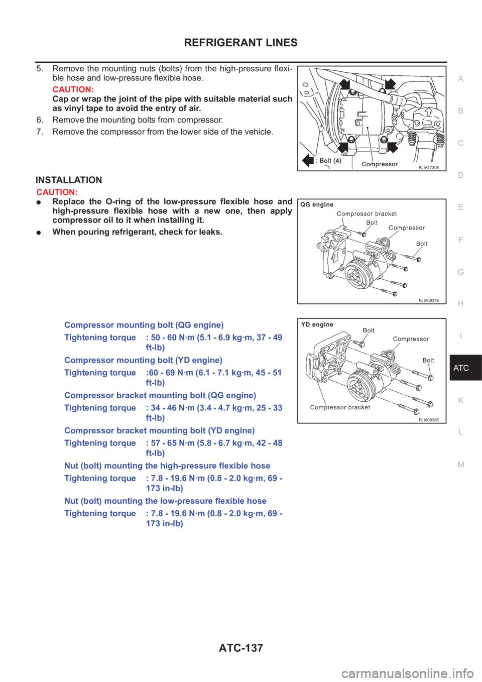
5. Remove the mounting nuts (bolts) from the high-pressure flexi-
ble hose and low-pressure flexible hose.
CAUTION:
Cap or wrap the joint of the pipe with suitable material such
as vinyl tape to avoid the entry of air.
6. Remove the mounting bolts from compressor.
7. Remove the compressor from the lower side of the vehicle.
INSTALLATION
CAUTION:
●Replace the O-ring of the low-pressure flexible hose and
high-pressure flexible hose with a new one, then apply
compressor oil to it when installing it.
●When pouring refrigerant, check for leaks.
RJIA1730E
RJIA0837E
Compressor mounting bolt (QG engine)
Tightening torque : 50 - 60 N·m (5.1 - 6.9 kg·m, 37 - 49
ft-lb)
Compressor mounting bolt (YD engine)
Tightening torque :60 - 69 N·m (6.1 - 7.1 kg·m, 45 - 51
ft-lb)
Compressor bracket mounting bolt (QG engine)
Tightening torque : 34 - 46 N·m (3.4 - 4.7 kg·m, 25 - 33
ft-lb)
Compressor bracket mounting bolt (YD engine)
Tightening torque : 57 - 65 N·m (5.8 - 6.7 kg·m, 42 - 48
ft-lb)
Nut (bolt) mounting the high-pressure flexible hose
Tightening torque : 7.8 - 19.6 N·m (0.8 - 2.0 kg·m, 69 -
173 in-lb)
Nut (bolt) mounting the low-pressure flexible hose
Tightening torque : 7.8 - 19.6 N·m (0.8 - 2.0 kg·m, 69 -
173 in-lb)
RJIA0838E
Page 2121 of 3189
REFRIGERANT LINES
ATC-141
C
D
E
F
G
H
I
K
L
MA
B
AT C
Break-In Operation
When replacing compressor clutch assembly, always carry out the break-in operation. This is done by engag-
ing and disengaging the clutch about thirty times. Break-in operation raises the level of transmitted torque.
Low-pressure Flexible HoseEJS0020M
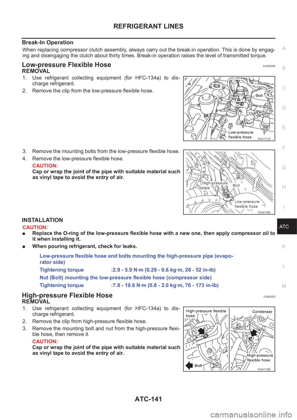
REMOVAL
1. Use refrigerant collecting equipment (for HFC-134a) to dis-
charge refrigerant.
2. Remove the clip from the low-pressure flexible hose.
3. Remove the mounting bolts from the low-pressure flexible hose.
4. Remove the low-pressure flexible hose.
CAUTION:
Cap or wrap the joint of the pipe with suitable material such
as vinyl tape to avoid the entry of air.
INSTALLATION
CAUTION:
●Replace the O-ring of the low-pressure flexible hose with a new one, then apply compressor oil to
it when installing it.
●When pouring refrigerant, check for leaks.
High-pressure Flexible HoseEJS0022Z
REMOVAL
1. Use refrigerant collecting equipment (for HFC-134a) to dis-
charge refrigerant.
2. Remove the clip from high-pressure flexible hose.
3. Remove the mounting bolt and nut from the high-pressure flexi-
ble hose, then remove it.
CAUTION:
Cap or wrap the joint of the pipe with suitable material such
as vinyl tape to avoid the entry of air.
RJIA1731E
RJIA0185E
Low-pressure flexible hose and bolts mounting the high-pressure pipe (evapo-
rator side)
Tightening torque :2.9 - 5.9 N·m (0.29 - 0.6 kg·m, 26 - 52 in-lb)
Nut (Bolt) mounting the low-pressure flexible hose (compressor side)
Tightening torque :7.8 - 19.6 N·m (0.8 - 2.0 kg·m, 70 - 173 in-lb)
RJIA1735E
Page 2122 of 3189
ATC-142
REFRIGERANT LINES
INSTALLATION
CAUTION:
●Replace the O-ring of the high-pressure flexible hose with a new one, then apply compressor oil to
it when installing it.
●When pouring refrigerant, check for leaks.
High-pressure PipeEJS00230
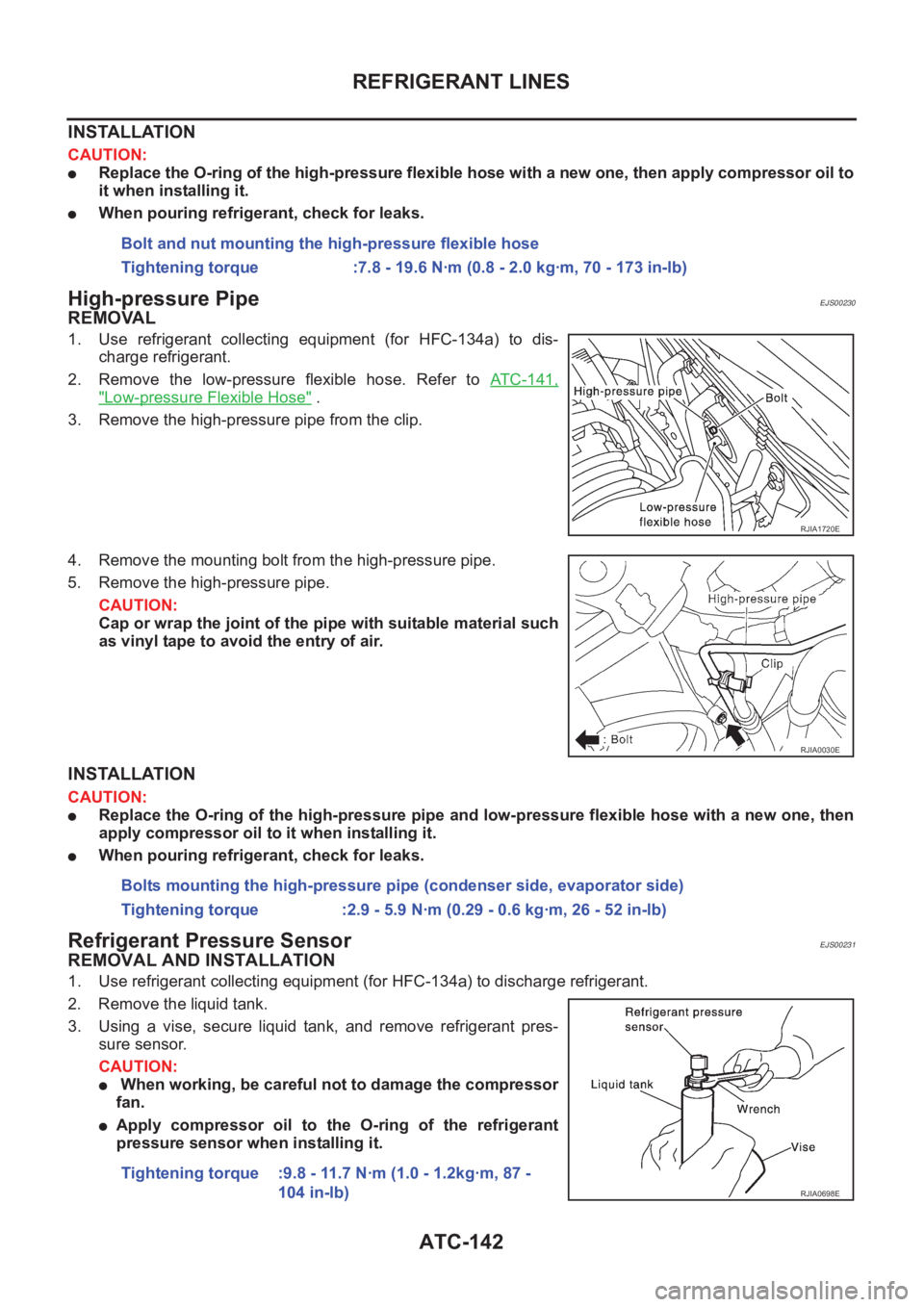
REMOVAL
1. Use refrigerant collecting equipment (for HFC-134a) to dis-
charge refrigerant.
2. Remove the low-pressure flexible hose. Refer to ATC-141,
"Low-pressure Flexible Hose" .
3. Remove the high-pressure pipe from the clip.
4. Remove the mounting bolt from the high-pressure pipe.
5. Remove the high-pressure pipe.
CAUTION:
Cap or wrap the joint of the pipe with suitable material such
as vinyl tape to avoid the entry of air.
INSTALLATION
CAUTION:
●Replace the O-ring of the high-pressure pipe and low-pressure flexible hose with a new one, then
apply compressor oil to it when installing it.
●When pouring refrigerant, check for leaks.
Refrigerant Pressure SensorEJS00231
REMOVAL AND INSTALLATION
1. Use refrigerant collecting equipment (for HFC-134a) to discharge refrigerant.
2. Remove the liquid tank.
3. Using a vise, secure liquid tank, and remove refrigerant pres-
sure sensor.
CAUTION:
● When working, be careful not to damage the compressor
fan.
●Apply compressor oil to the O-ring of the refrigerant
pressure sensor when installing it.Bolt and nut mounting the high-pressure flexible hose
Tightening torque :7.8 - 19.6 N·m (0.8 - 2.0 kg·m, 70 - 173 in-lb)
RJIA1720E
RJIA0030E
Bolts mounting the high-pressure pipe (condenser side, evaporator side)
Tightening torque :2.9 - 5.9 N·m (0.29 - 0.6 kg·m, 26 - 52 in-lb)
Tightening torque :9.8 - 11.7 N·m (1.0 - 1.2kg·m, 87 -
104 in-lb)
RJIA0698E
Page 2123 of 3189
REFRIGERANT LINES
ATC-143
C
D
E
F
G
H
I
K
L
MA
B
AT C
Dual-pressure SwitchEJS0020Q
REMOVAL AND INSTALLATION
1. Use refrigerant collecting equipment (for HFC-134a) to discharge refrigerant.
2. Remove the liquid tank.
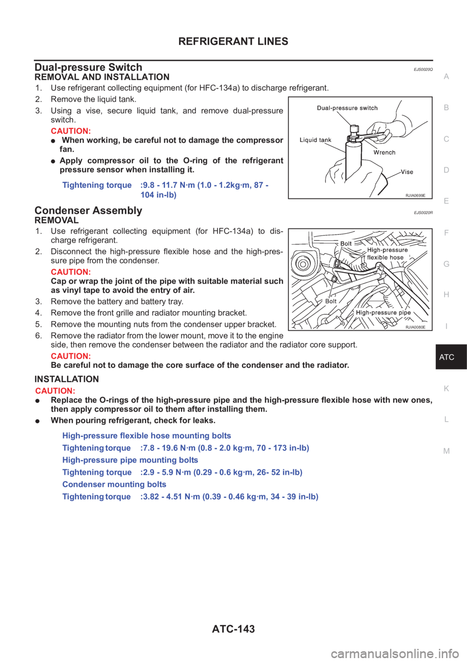
3. Using a vise, secure liquid tank, and remove dual-pressure
switch.
CAUTION:
● When working, be careful not to damage the compressor
fan.
●Apply compressor oil to the O-ring of the refrigerant
pressure sensor when installing it.
Condenser AssemblyEJS0020R
REMOVAL
1. Use refrigerant collecting equipment (for HFC-134a) to dis-
charge refrigerant.
2. Disconnect the high-pressure flexible hose and the high-pres-
sure pipe from the condenser.
CAUTION:
Cap or wrap the joint of the pipe with suitable material such
as vinyl tape to avoid the entry of air.
3. Remove the battery and battery tray.
4. Remove the front grille and radiator mounting bracket.
5. Remove the mounting nuts from the condenser upper bracket.
6. Remove the radiator from the lower mount, move it to the engine
side, then remove the condenser between the radiator and the radiator core support.
CAUTION:
Be careful not to damage the core surface of the condenser and the radiator.
INSTALLATION
CAUTION:
●Replace the O-rings of the high-pressure pipe and the high-pressure flexible hose with new ones,
then apply compressor oil to them after installing them.
●When pouring refrigerant, check for leaks.Tightening torque :9.8 - 11.7 N·m (1.0 - 1.2kg·m, 87 -
104 in-lb)
RJIA0699E
RJIA0080E
High-pressure flexible hose mounting bolts
Tightening torque :7.8 - 19.6 N·m (0.8 - 2.0 kg·m, 70 - 173 in-lb)
High-pressure pipe mounting bolts
Tightening torque :2.9 - 5.9 N·m (0.29 - 0.6 kg·m, 26- 52 in-lb)
Condenser mounting bolts
Tightening torque :3.82 - 4.51 N·m (0.39 - 0.46 kg·m, 34 - 39 in-lb)
Page 2124 of 3189
ATC-144
REFRIGERANT LINES
Evaporator
EJS0020S
REMOVAL
1. Use refrigerant collecting equipment (for HFC-134a) to dis-
charge refrigerant.
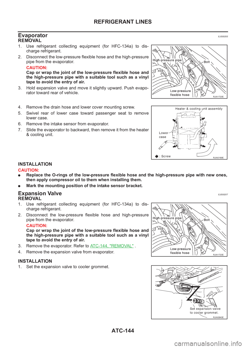
2. Disconnect the low-pressure flexible hose and the high-pressure
pipe from the evaporator.
CAUTION:
Cap or wrap the joint of the low-pressure flexible hose and
the high-pressure pipe with a suitable tool such as a vinyl
tape to avoid the entry of air.
3. Hold expansion valve and move it slightly upward. Push evapo-
rator toward rear of vehicle.
4. Remove the drain hose and lower cover mounting screw.
5. Swivel rear of lower case toward passenger seat to remove
lower case.
6. Remove the intake sensor from evaporator.
7. Slide the evaporator to backward, then remove it from the heater
& cooling unit.
INSTALLATION
CAUTION:
●Replace the O-rings of the low-pressure flexible hose and the high-pressure pipe with new ones,
then apply compressor oil to them when installing them.
●Mark the mounting position of the intake sensor bracket.
Expansion ValveEJS0020T
REMOVAL
1. Use refrigerant collecting equipment (for HFC-134a) to dis-
charge refrigerant.
2. Disconnect the low-pressure flexible hose and high-pressure
pipe from the evaporator.
CAUTION:
Cap or wrap the joint of the low-pressure flexible hose and
the high-pressure pipe with a suitable tool such as a vinyl
tape to avoid the entry of air.
3. Remove the evaporator. Refer to ATC-144, "
REMOVAL" .
4. Remove the expansion valve from evaporator.
INSTALLATION
1. Set the expansion valve to cooler grommet.
RJIA1720E
RJIA0189E
RJIA1720E
RJIA0840E
Page 2126 of 3189
ATC-146
REFRIGERANT LINES
Dye Injection
EJS0020W
(This procedure is only necessary when recharging the system or when the compressor has seized and was
replaced.)
1. Check A/C system static (at rest) pressure. Pressure must be at least 345 kPa (3.45 bar, 3.52kg/cm
2 , 50
psi).
2. Pour one bottle (1/4 ounce / 7.4 cc) of the A/C refrigerant dye into the injector tool (J-41459).
3. Connect the injector tool to the A/C LOW PRESSURE side service fitting.
4. Start engine and switch A/C ON.
5. When the A/C operating (compressor running), inject one bottle (1/4 ounce / 7.4 cc) of fluorescent dye
through the low-pressure service valve using dye injector tool J-41459 (refer to the manufacture′s operat-
ing instructions).
6. With the engine still running, disconnect the injector tool from the service fitting.
CAUTION:
Be careful the A/C system or replacing a component, pour the dye directly into the open system con-
nection and proceed with the service procedures.
7. Operate the A/C system for a minimum of 20 minutes to mix the dye with the system oil. Depending on the
leak size, operating conditions and location of the leak, it may take from minutes to days for the dye to
penetrate a leak and become visible.
Electronic Refrigerant Leak DetectorEJS0020X
PRECAUTIONS FOR HANDLING LEAK DETECTOR
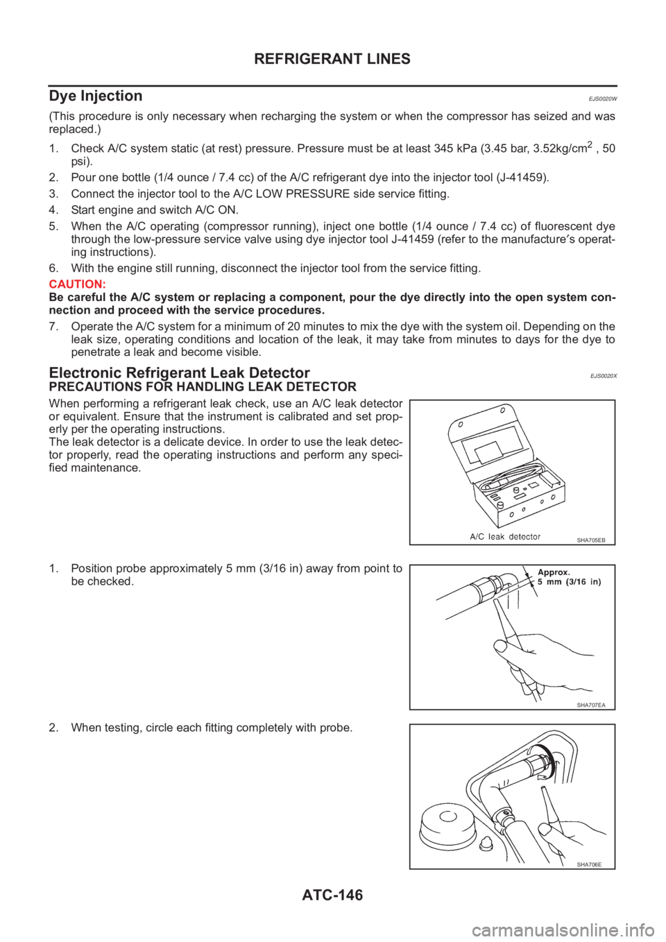
When performing a refrigerant leak check, use an A/C leak detector
or equivalent. Ensure that the instrument is calibrated and set prop-
erly per the operating instructions.
The leak detector is a delicate device. In order to use the leak detec-
tor properly, read the operating instructions and perform any speci-
fied maintenance.
1. Position probe approximately 5 mm (3/16 in) away from point to
be checked.
2. When testing, circle each fitting completely with probe.
SHA705EB
SHA707EA
SHA706E
Page 2380 of 3189
YEL809D
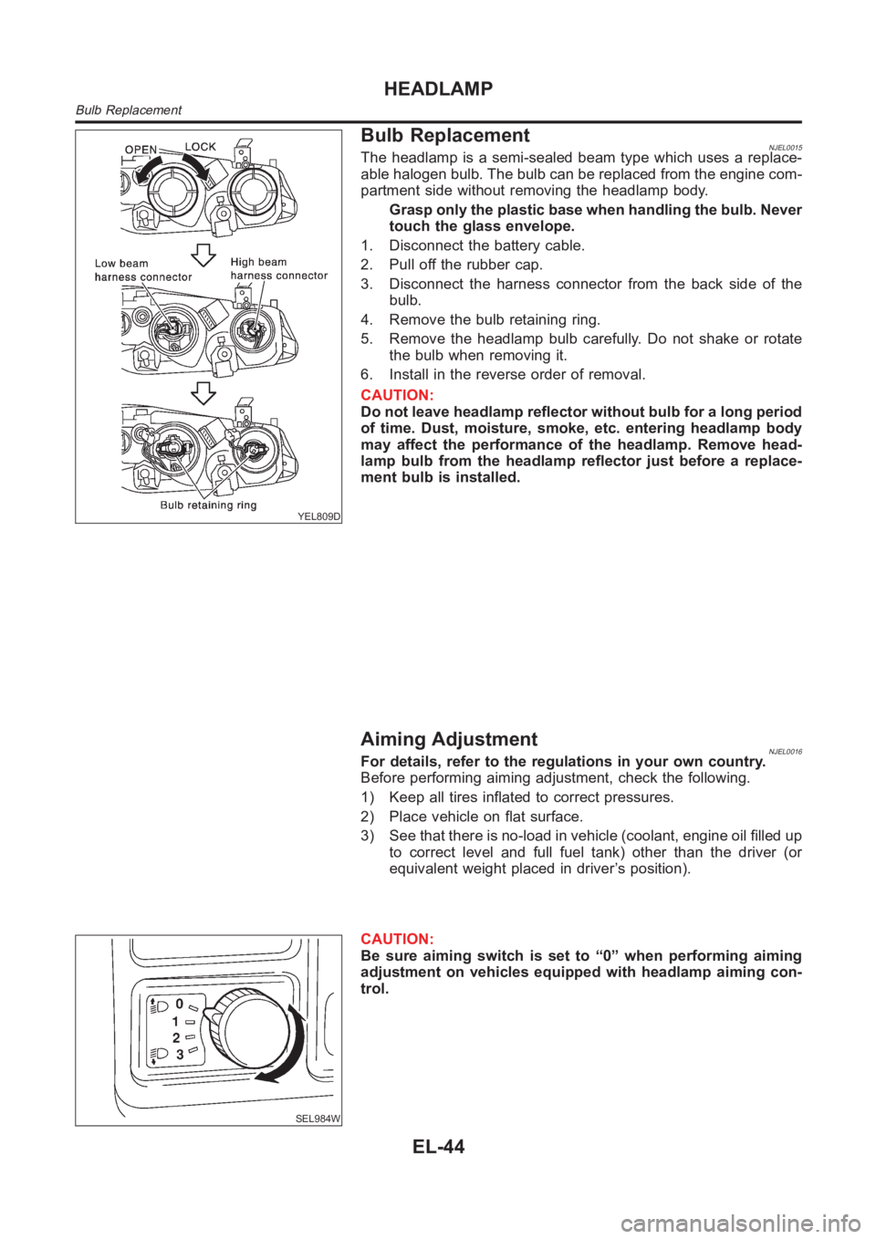
Bulb ReplacementNJEL0015The headlamp is a semi-sealed beam type which uses a replace-
able halogen bulb. The bulb can be replaced from the engine com-
partment side without removing the headlamp body.
Grasp only the plastic base when handling the bulb. Never
touch the glass envelope.
1. Disconnect the battery cable.
2. Pull off the rubber cap.
3. Disconnect the harness connector from the back side of the
bulb.
4. Remove the bulb retaining ring.
5. Remove the headlamp bulb carefully. Do not shake or rotate
the bulb when removing it.
6. Install in the reverse order of removal.
CAUTION:
Do not leave headlamp reflector without bulb for a long period
of time. Dust, moisture, smoke, etc. entering headlamp body
may affect the performance of the headlamp. Remove head-
lamp bulb from the headlamp reflector just before a replace-
ment bulb is installed.
Aiming AdjustmentNJEL0016For details, refer to the regulations in your own country.
Before performing aiming adjustment, check the following.
1) Keep all tires inflated to correct pressures.
2) Place vehicle on flat surface.
3) See that there is no-load in vehicle (coolant, engine oil filled up
to correct level and full fuel tank) other than the driver (or
equivalent weight placed in driver’s position).
SEL984W
CAUTION:
Be sure aiming switch is set to “0” when performing aiming
adjustment on vehicles equipped with headlamp aiming con-
trol.
HEADLAMP
Bulb Replacement
EL-44