Page 1260 of 3189

Diagnostic ProcedureNJEC0770
1 CHECK START SIGNAL OVERALL FUNCTION
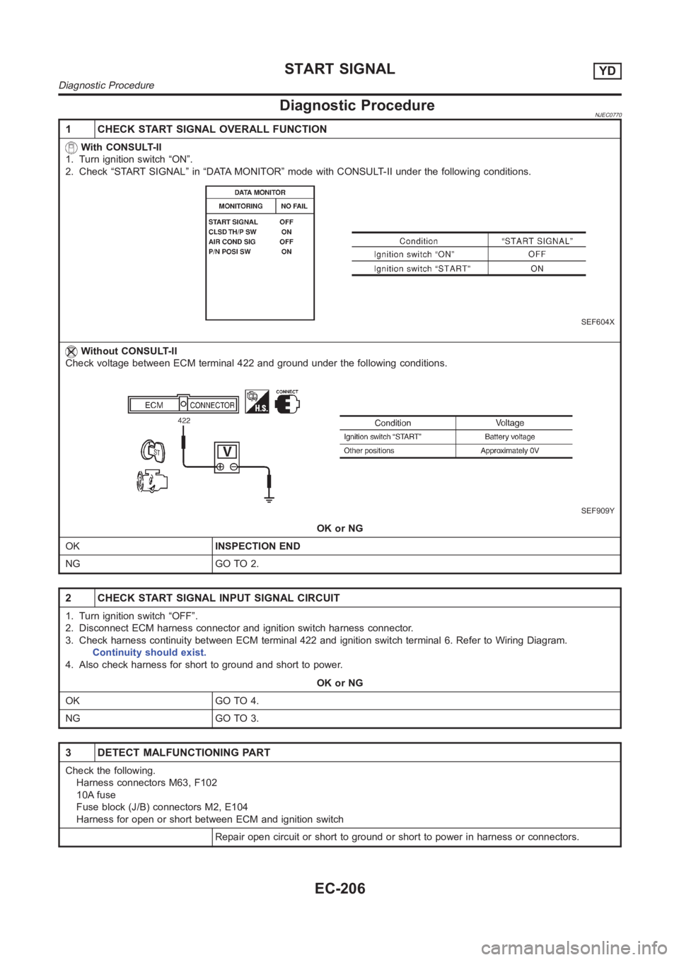
With CONSULT-II
1. Turn ignition switch “ON”.
2. Check “START SIGNAL” in “DATA MONITOR” mode with CONSULT-II under the following conditions.
SEF604X
Without CONSULT-II
Check voltage between ECM terminal 422 and ground under the following conditions.
SEF909Y
OK or NG
OKINSPECTION END
NG GO TO 2.
2 CHECK START SIGNAL INPUT SIGNAL CIRCUIT
1. Turn ignition switch “OFF”.
2. Disconnect ECM harness connector and ignition switch harness connector.
3. Check harness continuity between ECM terminal 422 and ignition switch terminal 6. Refer to Wiring Diagram.
Continuity should exist.
4. Also check harness for short to ground and short to power.
OK or NG
OK GO TO 4.
NG GO TO 3.
3 DETECT MALFUNCTIONING PART
Check the following.
Harness connectors M63, F102
10A fuse
Fuse block (J/B) connectors M2, E104
Harness for open or short between ECM and ignition switch
Repair open circuit or short to ground or short to power in harness or connectors.
START SIGNALYD
Diagnostic Procedure
EC-206
Page 1346 of 3189

NJMT0090
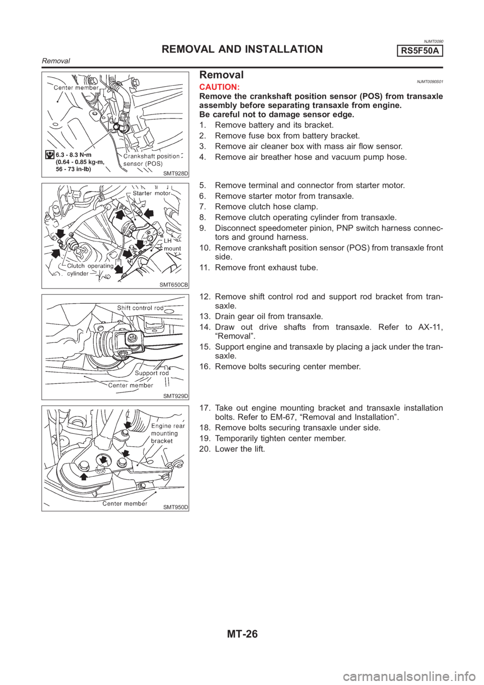
SMT928D
RemovalNJMT0090S01CAUTION:
Remove the crankshaft position sensor (POS) from transaxle
assembly before separating transaxle from engine.
Be careful not to damage sensor edge.
1. Remove battery and its bracket.
2. Remove fuse box from battery bracket.
3. Remove air cleaner box with mass air flow sensor.
4. Remove air breather hose and vacuum pump hose.
SMT650CB
5. Remove terminal and connector from starter motor.
6. Remove starter motor from transaxle.
7. Remove clutch hose clamp.
8. Remove clutch operating cylinder from transaxle.
9. Disconnect speedometer pinion, PNP switch harness connec-
tors and ground harness.
10. Remove crankshaft position sensor (POS) from transaxle front
side.
11. Remove front exhaust tube.
SMT929D
12. Remove shift control rod and support rod bracket from tran-
saxle.
13. Drain gear oil from transaxle.
14. Draw out drive shafts from transaxle. Refer to AX-11,
“Removal”.
15. Support engine and transaxle by placing a jack under the tran-
saxle.
16. Remove bolts securing center member.
SMT950D
17. Take out engine mounting bracket and transaxle installation
bolts. Refer to EM-67, “Removal and Installation”.
18. Remove bolts securing transaxle under side.
19. Temporarily tighten center member.
20. Lower the lift.
REMOVAL AND INSTALLATIONRS5F50A
Removal
MT-26
Page 1570 of 3189
AT-114
[EURO-OBD]
DTC P0705 PARK/NEUTRAL POSITION (PNP) SWITCH
Diagnostic Procedure
ECS007O6
1. INSPECTION START
Do you have CONSULT-II?
Ye s o r N o
Yes >> GO TO 2
No >> GO TO 3
2. CHECK PNP SWITCH CIRCUIT (WITH CONSULT-II)
With CONSULT-II
1. Turn ignition switch to “ON” position.
(Do not start engine.)
2. Select “TCM INPUT SIGNALS” in “DATA MONITOR” mode for
“A/T” with CONSULT-II.
3. Read out “P/N”, “R”, “D”, “2” and “1” position switches moving
selector lever to each position.
Check the signal of the selector lever position is indicated prop-
erly.
OK or NG
OK >> GO TO 4
NG >> Check the following items:
●PNP switch
Refer to AT- 11 6 , "
Component Inspection" .
●Harness for short or open between ignition switch and
PNP switch
●Harness for short or open between PNP switch and
TCM
●Ignition switch and fuse
Refer to EL-11, "POWER SUPPLY ROUTING".
●Diode (P, N positions)
SAT014K
SAT701J
Page 1571 of 3189
DTC P0705 PARK/NEUTRAL POSITION (PNP) SWITCH
AT-115
[EURO-OBD]
D
E
F
G
H
I
J
K
L
MA
B
AT
3.CHECK PNP SWITCH CIRCUIT (WITHOUT CONSULT-II)
Without CONSULT-II
1. Turn ignition switch to “ON” position.
(Do not start engine.)
2. Check voltage between TCM terminals 26, 27, 34, 35, 36 and ground while moving selector lever through
each position.
OK or NG
OK >> GO TO 4
NG >> Check the following items:
●PNP switch
Refer to AT-116, "
Component Inspection" .
●Harness for short or open between ignition switch and PNP switch
●Harness for short or open between PNP switch and TCM
●Ignition switch and fuse
Refer to EL-11, "POWER SUPPLY ROUTING".
●Diode (P, N positions) Vo l t a g e :
B: Battery voltage
0: 0V
MTBL0136
SCIA0753E
Page 1654 of 3189
![NISSAN ALMERA N16 2003 Electronic Repair Manual AT-198
[EURO-OBD]
DTC BATT/FLUID TEMP SEN (A/T FLUID TEMP SENSOR CIRCUIT AND TCM
POWER SOURCE)
Diagnostic Procedure
ECS007PS
1. CHECK TCM POWER SOURCE
1. Turn ignition switch to “ON” position.
(D NISSAN ALMERA N16 2003 Electronic Repair Manual AT-198
[EURO-OBD]
DTC BATT/FLUID TEMP SEN (A/T FLUID TEMP SENSOR CIRCUIT AND TCM
POWER SOURCE)
Diagnostic Procedure
ECS007PS
1. CHECK TCM POWER SOURCE
1. Turn ignition switch to “ON” position.
(D](/manual-img/5/57350/w960_57350-1653.png)
AT-198
[EURO-OBD]
DTC BATT/FLUID TEMP SEN (A/T FLUID TEMP SENSOR CIRCUIT AND TCM
POWER SOURCE)
Diagnostic Procedure
ECS007PS
1. CHECK TCM POWER SOURCE
1. Turn ignition switch to “ON” position.
(Do not start engine.)
2. Check voltage between TCM terminals 10, 19, 28 and ground.
3. Turn ignition switch to “OFF” position.
4. Check voltage between TCM terminal 28 and ground.
OK or NG
OK >> GO TO 2
NG >> Check the following items:
●Harness for short or open between ignition switch and
TCM
●Ignition switch and fuse
Refer to EL-11, "POWER SUPPLY ROUTING".
2. CHECK A/T FLUID TEMPERATURE SENSOR WITH TERMINAL CORD ASSEMBLY
1. Turn ignition switch to “OFF” position.
2. Disconnect terminal cord assembly connector in engine compartment.
3. Check resistance between terminals 6 and 7 when A/T is cold.
4. Reinstall any part removed.
OK or NG
OK (With CONSULT-II)>>GO TO 3
OK (Without CONSULT-II)>>GOTO4
NG >> 1. Remove oil pan refer to AT-406, "
REMOVAL"
2. Check the following items:
–A/T fluid temperature sensor
Refer to AT-200, "
Component Inspection" .
–Harness of terminal cord assembly for short or open Voltage: Battery voltage
Voltage: Battery voltage
SCIA0736E
Resistance: Cold [20°C (68°F)]
Approximately 2.5 kΩ
SAT912JB
Page 1798 of 3189
AT-342
[ALL]
MAIN POWER SUPPLY AND GROUND CIRCUIT
3. DETECT MALFUNCTIONING ITEM
Check the following items:
●Harness for short or open between ignition switch and TCM terminals 10, 19 and 28
●Fuse
●Ignition switch
Refer to EL-11,"POWER SUPPLY ROUTING".
OK or NG
OK >> GO TO 4
NG >> Repair or replace damaged parts.
4. CHECK TCM GROUND CIRCUIT
1. Turn ignition switch to OFF position.
2. Disconnect TCM harness connector.
3. Check continuity between TCM terminals 25, 48 and ground. Refer to AT- 3 4 0 , "
Wiring Diagram — AT —
MAIN" .
If OK, check harness for short to ground and short to power.
OK or NG
OK >>INSPECTION END
NG >> Repair open circuit or short to ground or short to power in harness or connectors. Continuity should exist.
Page 1836 of 3189
![NISSAN ALMERA N16 2003 Electronic Repair Manual AT-380
[ALL]
BATT/FLUID TEMP SEN (A/T FLUID TEMP SENSOR CIRCUIT AND TCM POW-
ER SOURCE)
Diagnostic Procedure
ECS007SE
1. CHECK TCM POWER SOURCE
1. Turn ignition switch to “ON” position.
(Do not st NISSAN ALMERA N16 2003 Electronic Repair Manual AT-380
[ALL]
BATT/FLUID TEMP SEN (A/T FLUID TEMP SENSOR CIRCUIT AND TCM POW-
ER SOURCE)
Diagnostic Procedure
ECS007SE
1. CHECK TCM POWER SOURCE
1. Turn ignition switch to “ON” position.
(Do not st](/manual-img/5/57350/w960_57350-1835.png)
AT-380
[ALL]
BATT/FLUID TEMP SEN (A/T FLUID TEMP SENSOR CIRCUIT AND TCM POW-
ER SOURCE)
Diagnostic Procedure
ECS007SE
1. CHECK TCM POWER SOURCE
1. Turn ignition switch to “ON” position.
(Do not start engine.)
2. Check voltage between TCM terminals 10, 19, 28 and ground.
3. Turn ignition switch to “OFF” position.
4. Check voltage between TCM terminal 28 and ground.
OK or NG
OK >> GO TO 2
NG >> Check the following items:
●Harness for short or open between ignition switch and
TCM
●Ignition switch and fuse
Refer to EL-11, “POERT SUPPLY ROUTING".
2. CHECK A/T FLUID TEMPERATURE SENSOR WITH TERMINAL CORD ASSEMBLY
1. Turn ignition switch to “OFF” position.
2. Disconnect terminal cord assembly connector in engine compartment.
3. Check resistance between terminals 6 and 7 when A/T is cold.
4. Reinstall any part removed.
OK or NG
OK (With CONSULT-II)>>GO TO 3
OK (Without CONSULT-II)>>GO TO 4
NG >> 1. Remove oil pan, refer to AT- 4 0 6 , "
Control Valve
Assembly and Accumulators" .
2. Check the following items:
A/T fluid temperature sensor
Refer to AT-382, "
Component Inspection" .
Harness of terminal cord assembly for short or open Voltage: Battery voltage
Voltage: Battery voltage
SCIA0736E
Resistance: Cold[20°C(68°F)]
Approximately 2.5 kΩ
SAT912JB
Page 1856 of 3189
![NISSAN ALMERA N16 2003 Electronic Repair Manual AT-400
[ALL]
A/T SHIFT LOCK SYSTEM
Diagnostic Procedure
ECS007SV
SYMPTOM 1:
●Selector lever cannot be moved from “P” position with key in ON position and brake pedal
applied.
●Selec NISSAN ALMERA N16 2003 Electronic Repair Manual AT-400
[ALL]
A/T SHIFT LOCK SYSTEM
Diagnostic Procedure
ECS007SV
SYMPTOM 1:
●Selector lever cannot be moved from “P” position with key in ON position and brake pedal
applied.
●Selec](/manual-img/5/57350/w960_57350-1855.png)
AT-400
[ALL]
A/T SHIFT LOCK SYSTEM
Diagnostic Procedure
ECS007SV
SYMPTOM 1:
●Selector lever cannot be moved from “P” position with key in ON position and brake pedal
applied.
●Selector lever can be moved from “P” position with key in ON position and brake pedal released.
●Selector lever can be moved from “P” position when key is removed from key cylinder.
SYMPTOM 2:
Ignition key cannot be removed when selector lever is set to “P” position. It can be removed when
selector lever is set to any position except “P”.
1. CHECK KEY INTERLOCK CABLE
Check key interlock cable for damage.
OK or NG
OK >> GO TO 2
NG >> Repair key interlock cable. Refer to AT- 4 0 4 , "
KEY INTERLOCK CABLE" .
2. CHECK SELECTOR LEVER POSITION
Check selector lever position for damage.
OK or NG
OK >> GO TO 3
NG >> Check selector lever. Refer to AT- 4 0 8 , "
Park/Neutral Position (PNP) Switch Adjustment" .
3. CHECK POWER SOURCE
1. Turn ignition switch to “ON” position.
(Do not start engine.)
2. Check voltage between stop lamp switch harness terminal 1 and ground.
OK or NG
OK >> GO TO 4
NG >> Check the following items:
1. Harness for short or open between battery and stop
lamp switch harness terminal 1
2. Fuse
3. Ignition switch (Refer to EL-11, "POWER SUPPLY
ROUTING".) Voltage: Battery voltage
MCIB0003E