2003 NISSAN ALMERA N16 wheels
[x] Cancel search: wheelsPage 2164 of 3189
SMA525A
On-vehicle Service
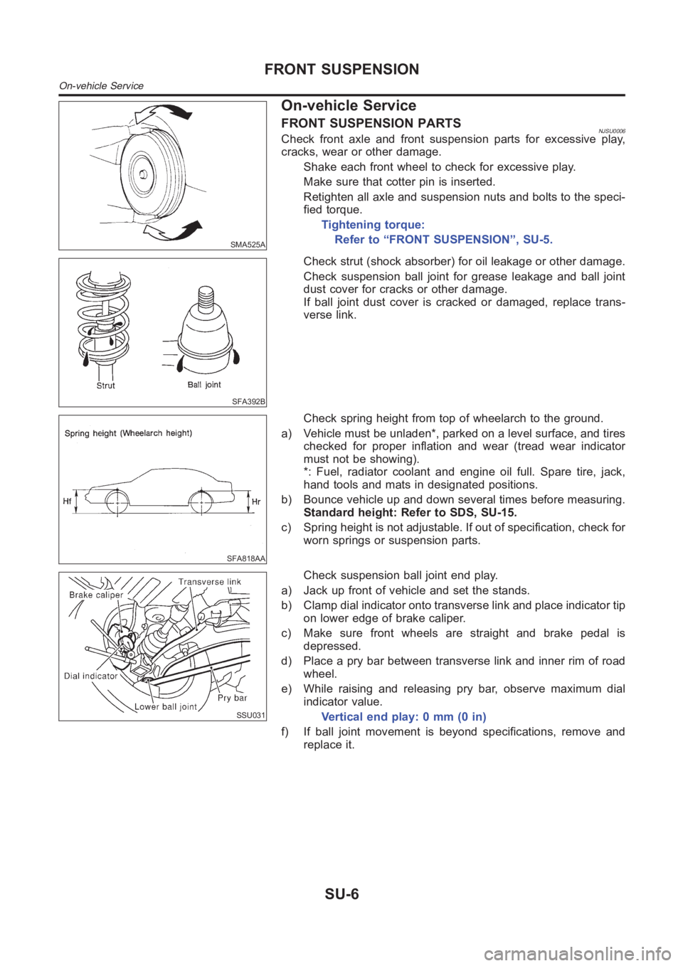
FRONT SUSPENSION PARTSNJSU0006Check front axle and front suspension parts for excessive play,
cracks, wear or other damage.
Shake each front wheel to check for excessive play.
Make sure that cotter pin is inserted.
Retighten all axle and suspension nuts and bolts to the speci-
fied torque.
Tightening torque:
Refer to “FRONT SUSPENSION”, SU-5.
SFA392B
Check strut (shock absorber) for oil leakage or other damage.
Check suspension ball joint for grease leakage and ball joint
dust cover for cracks or other damage.
If ball joint dust cover is cracked or damaged, replace trans-
verse link.
SFA818AA
Check spring height from top of wheelarch to the ground.
a) Vehicle must be unladen*, parked on a level surface, and tires
checked for proper inflation and wear (tread wear indicator
must not be showing).
*: Fuel, radiator coolant and engine oil full. Spare tire, jack,
hand tools and mats in designated positions.
b) Bounce vehicle up and down several times before measuring.
Standard height: Refer to SDS, SU-15.
c) Spring height is not adjustable. If out of specification, check for
worn springs or suspension parts.
SSU031
Check suspension ball joint end play.
a) Jack up front of vehicle and set the stands.
b) Clamp dial indicator onto transverse link and place indicator tip
on lower edge of brake caliper.
c) Make sure front wheels are straight and brake pedal is
depressed.
d) Place a pry bar between transverse link and inner rim of road
wheel.
e) While raising and releasing pry bar, observe maximum dial
indicator value.
Vertical end play: 0 mm (0 in)
f) If ball joint movement is beyond specifications, remove and
replace it.
FRONT SUSPENSION
On-vehicle Service
SU-6
Page 2165 of 3189
SFA975B
BALANCING WHEELSNJSU0042Preliminary InspectionNJSU0042S011. Check tires for wear and improper inflation.
2. Check wheels for deformation, cracks and other damage.
If deformed, remove wheel and check wheel runout.
a. Remove tire from wheel and mount wheel on a tire balance
machine.
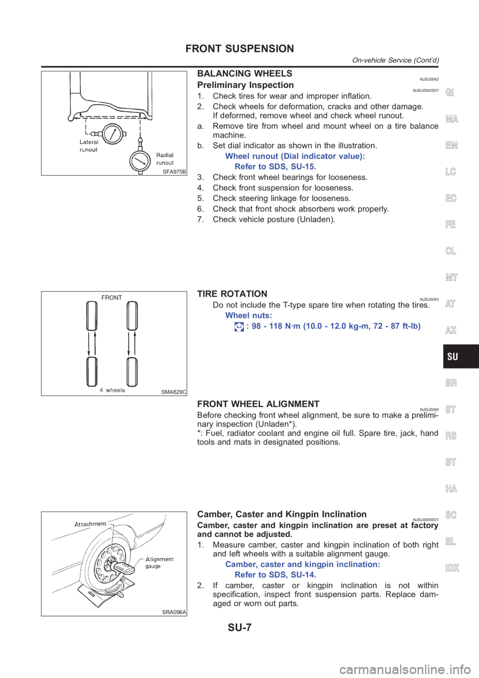
b. Set dial indicator as shown in the illustration.
Wheel runout (Dial indicator value):
Refer to SDS, SU-15.
3. Check front wheel bearings for looseness.
4. Check front suspension for looseness.
5. Check steering linkage for looseness.
6. Check that front shock absorbers work properly.
7. Check vehicle posture (Unladen).
SMA829C
TIRE ROTATIONNJSU0043Do not include the T-type spare tire when rotating the tires.
Wheel nuts:
: 98 - 118 N·m (10.0 - 12.0 kg-m, 72 - 87 ft-lb)
FRONT WHEEL ALIGNMENTNJSU0045Before checking front wheel alignment, be sure to make a prelimi-
nary inspection (Unladen*).
*: Fuel, radiator coolant and engine oil full. Spare tire, jack, hand
tools and mats in designated positions.
SRA096A
Camber, Caster and Kingpin InclinationNJSU0045S01Camber, caster and kingpin inclination are preset at factory
and cannot be adjusted.
1. Measure camber, caster and kingpin inclination of both right
and left wheels with a suitable alignment gauge.
Camber, caster and kingpin inclination:
Refer to SDS, SU-14.
2. If camber, caster or kingpin inclination is not within
specification, inspect front suspension parts. Replace dam-
aged or worn out parts.
GI
MA
EM
LC
EC
FE
CL
MT
AT
AX
BR
ST
RS
BT
HA
SC
EL
IDX
FRONT SUSPENSION
On-vehicle Service (Cont’d)
SU-7
Page 2166 of 3189
AFA050
To e - i nNJSU0045S02Measure toe-in using the following procedure.
WARNING:
Always perform the following procedure on a flat surface.
Make sure that no person is in front of the vehicle before
pushing it.
1. Bounce front of vehicle up and down to stabilize the posture.
2. Push the vehicle straight ahead about 5 m (16 ft).
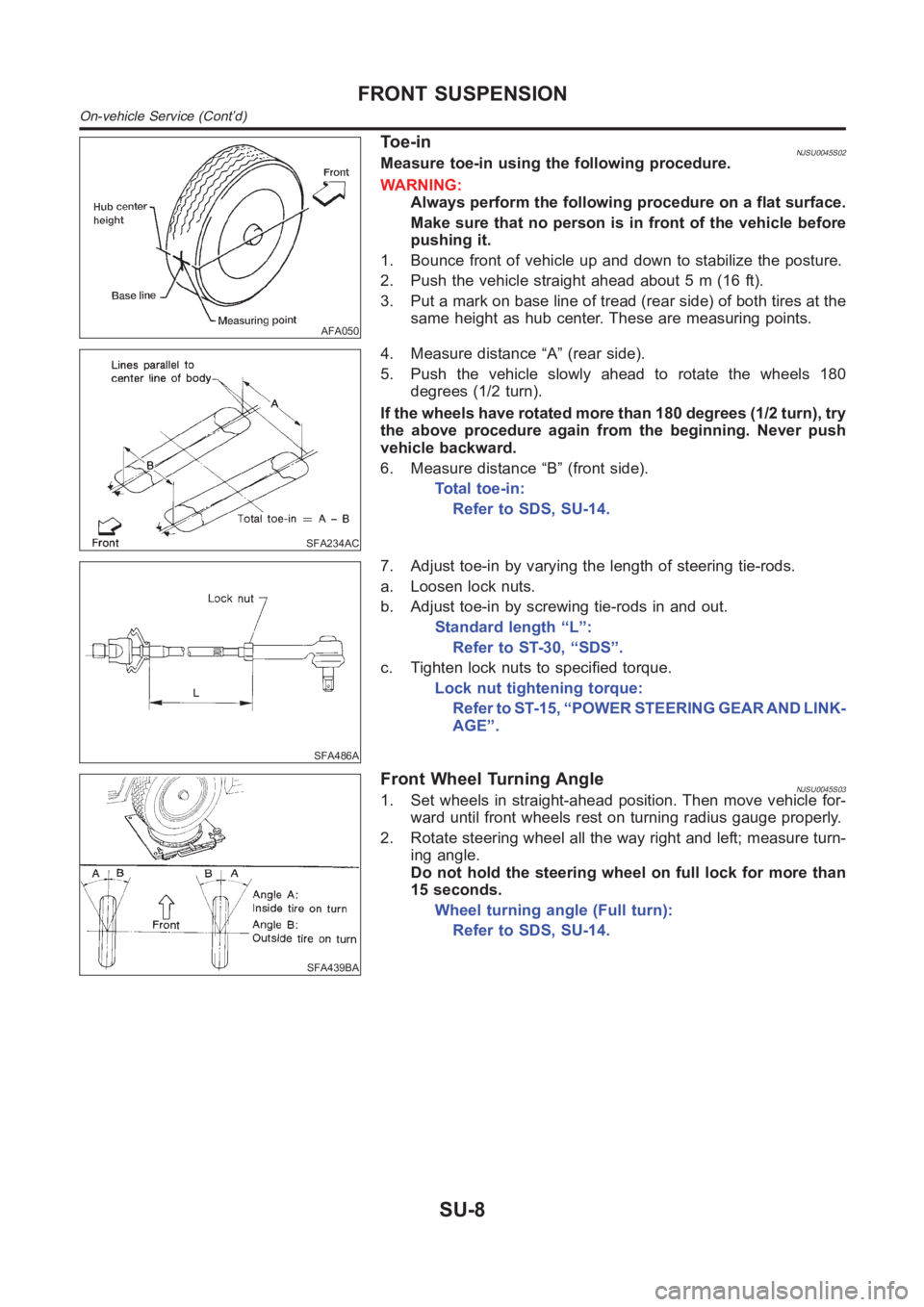
3. Put a mark on base line of tread (rear side) of both tires at the
same height as hub center. These are measuring points.
SFA234AC
4. Measure distance “A” (rear side).
5. Push the vehicle slowly ahead to rotate the wheels 180
degrees (1/2 turn).
If the wheels have rotated more than 180 degrees (1/2 turn), try
the above procedure again from the beginning. Never push
vehicle backward.
6. Measure distance “B” (front side).
Total toe-in:
Refer to SDS, SU-14.
SFA486A
7. Adjust toe-in by varying the length of steering tie-rods.
a. Loosen lock nuts.
b. Adjust toe-in by screwing tie-rods in and out.
Standard length “L”:
Refer to ST-30, “SDS”.
c. Tighten lock nuts to specified torque.
Lock nut tightening torque:
Refer to ST-15, “POWER STEERING GEAR AND LINK-
AGE”.
SFA439BA
Front Wheel Turning AngleNJSU0045S031. Set wheels in straight-ahead position. Then move vehicle for-
ward until front wheels rest on turning radius gauge properly.
2. Rotate steering wheel all the way right and left; measure turn-
ing angle.
Do not hold the steering wheel on full lock for more than
15 seconds.
Wheel turning angle (Full turn):
Refer to SDS, SU-14.
FRONT SUSPENSION
On-vehicle Service (Cont’d)
SU-8
Page 2176 of 3189

SMA525A
On-vehicle Service
REAR SUSPENSION PARTSNJSU0029Check axle and suspension parts for excessive play, wear or dam-
age.
Shake each rear wheel to check for excessive play.
SSU036
Retighten all nuts and bolts to the specified torque.
Tightening torque:
Refer to “REAR SUSPENSION”, SU-17.
SMA113
Check shock absorber for oil leakage or other damage.
Check wheelarch height. Refer to “On-vehicle Service”,
“FRONT SUSPENSION PARTS”, SU-6.
REAR WHEEL ALIGNMENTNJSU0030Before checking rear wheel alignment, be sure to make a prelimi-
nary inspection (Unladen*).
*: Fuel, radiator coolant and engine oil full. Spare tire, jack, hand
tools and mats in designated positions.
SFA975B
Preliminary InspectionNJSU0030S011. Check tires for wear and improper inflation.
2. Check wheels for deformation, cracks and other damage.
If deformed, remove wheel and check wheel runout.
a. Remove tire from wheel and mount wheel on a tire balance
machine.
b. Set dial indicator as shown in the illustration.
Wheel runout (Dial indicator value):
Refer to SDS, SU-15.
3. Check front wheel bearings for looseness.
REAR SUSPENSION
On-vehicle Service
SU-18
Page 2177 of 3189
4. Check front suspension for looseness.
5. Check steering linkage for looseness.
6. Check that front shock absorbers work properly.
7. Check vehicle posture (Unladen).
SFA948A
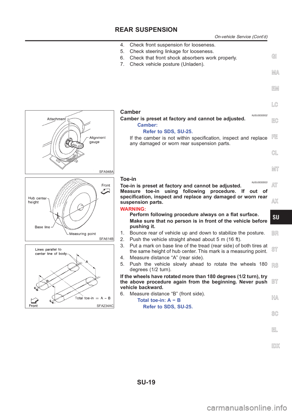
CamberNJSU0030S02Camber is preset at factory and cannot be adjusted.
Camber:
Refer to SDS, SU-25.
If the camber is not within specification, inspect and replace
any damaged or worn rear suspension parts.
SFA614B
SFA234AC
To e - i nNJSU0030S03Toe-in is preset at factory and cannot be adjusted.
Measure toe-in using following procedure. If out of
specification, inspect and replace any damaged or worn rear
suspension parts.
WARNING:
Perform following procedure always on a flat surface.
Make sure that no person is in front of the vehicle before
pushing it.
1. Bounce rear of vehicle up and down to stabilize the posture.
2. Push the vehicle straight ahead about 5 m (16 ft).
3. Put a mark on base line of the tread (rear side) of both tires at
the same height of hub center. This mark is a measuring point.
4. Measure distance “A” (rear side).
5. Push the vehicle slowly ahead to rotate the wheels 180
degrees (1/2 turn).
If the wheels have rotated more than 180 degrees (1/2 turn), try
the above procedure again from the beginning. Never push
vehicle backward.
6. Measure distance “B” (front side).
Total toe-in: A − B
Refer to SDS, SU-25.
GI
MA
EM
LC
EC
FE
CL
MT
AT
AX
BR
ST
RS
BT
HA
SC
EL
IDX
REAR SUSPENSION
On-vehicle Service (Cont’d)
SU-19
Page 2229 of 3189
PurposeNJBR0082The ABS consists of electronic and hydraulic components. It allows for control of braking force so that lock-
ing of the wheels can be avoided.
The ABS:
1) Ensures proper tracking performance through steering wheel operation.
2) Enables obstacles to be avoided through steering wheel operation.
3) Ensures vehicle stability by preventing flat spins.
ABS (Anti-Lock Brake System) OperationNJBR0083When the vehicle speed is less than 10 km/h (6 MPH) this system does not work.
The Anti-Lock Brake System (ABS) has self-test capabilities. The system turns on the ABS warning lamp
for 1 second after turning the ignition switch ON. The system performs another test the first time the vehicle
reaches 6 km/h (4 MPH). A mechanical noise may be heard as the ABS performs a self-test. This is a
normal part of the self-test feature. If a malfunction is found during thischeck, the ABS warning lamp will
come on.
During ABS operation, a mechanical noise may be heard. This is a normal condition.
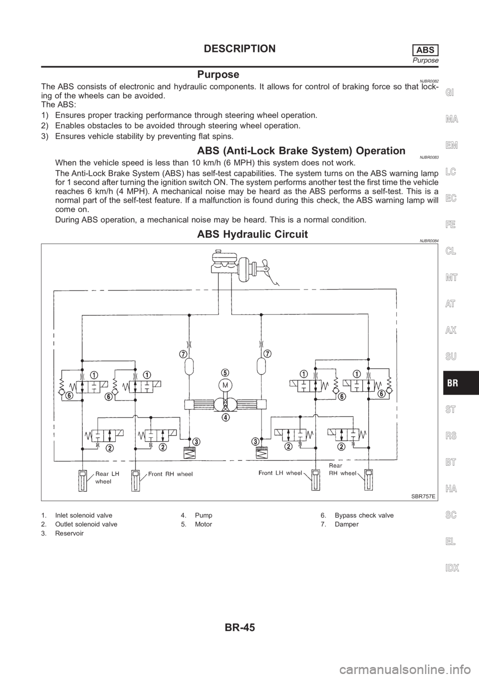
ABS Hydraulic CircuitNJBR0084
SBR757E
1. Inlet solenoid valve
2. Outlet solenoid valve
3. Reservoir4. Pump
5. Motor6. Bypass check valve
7. Damper
GI
MA
EM
LC
EC
FE
CL
MT
AT
AX
SU
ST
RS
BT
HA
SC
EL
IDX
DESCRIPTIONABS
Purpose
BR-45
Page 2231 of 3189
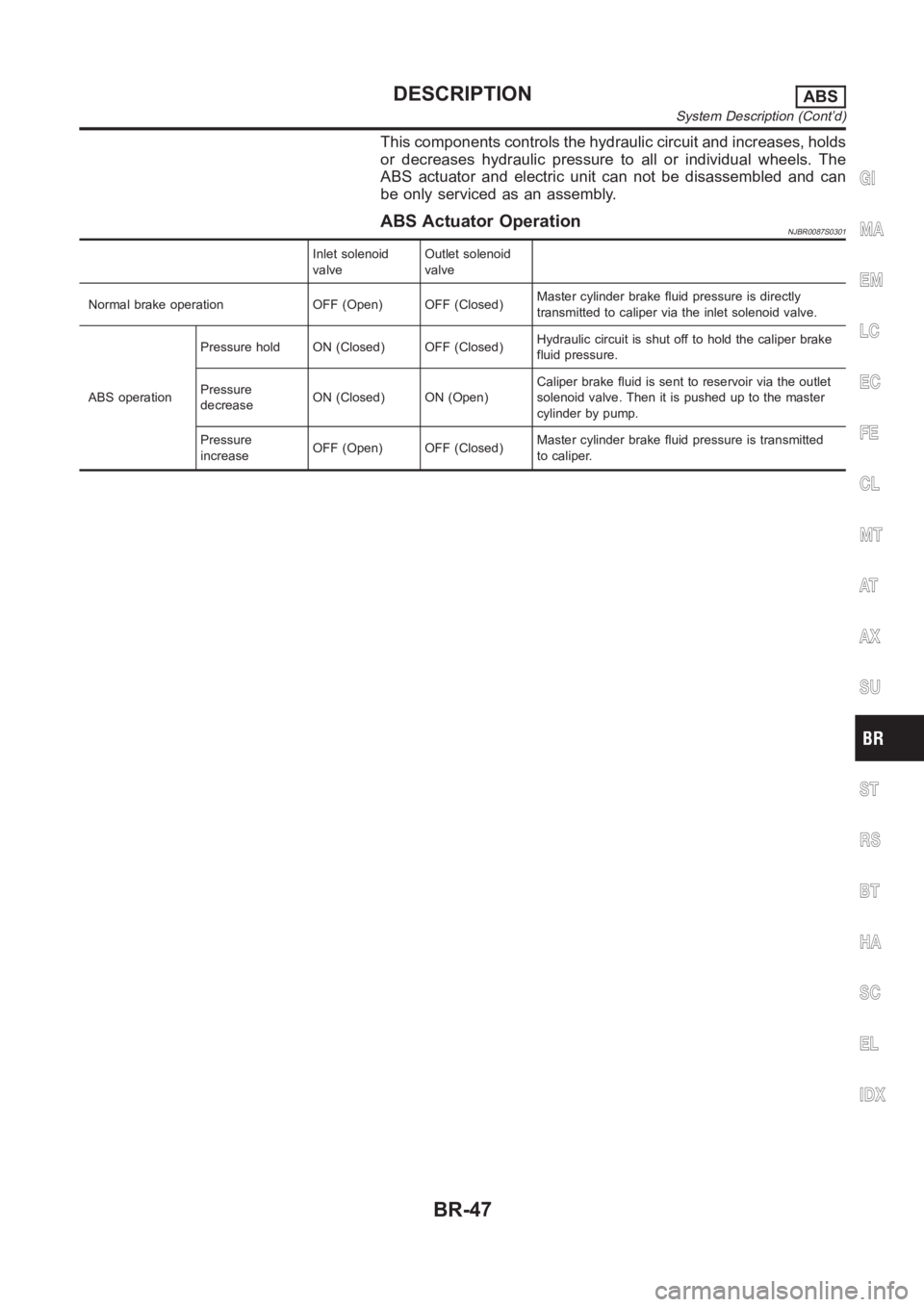
This components controls the hydraulic circuit and increases, holds
or decreases hydraulic pressure to all or individual wheels. The
ABS actuator and electric unit can not be disassembled and can
be only serviced as an assembly.
ABS Actuator OperationNJBR0087S0301
Inlet solenoid
valveOutlet solenoid
valve
Normal brake operation OFF (Open) OFF (Closed)Master cylinder brake fluid pressure is directly
transmitted to caliper via the inlet solenoid valve.
ABS operationPressure hold ON (Closed) OFF (Closed)Hydraulic circuit is shut off to hold the caliper brake
fluid pressure.
Pressure
decreaseON (Closed) ON (Open)Caliper brake fluid is sent to reservoir via the outlet
solenoid valve. Then it is pushed up to the master
cylinder by pump.
Pressure
increaseOFF (Open) OFF (Closed)Master cylinder brake fluid pressure is transmitted
to caliper.
GI
MA
EM
LC
EC
FE
CL
MT
AT
AX
SU
ST
RS
BT
HA
SC
EL
IDX
DESCRIPTIONABS
System Description (Cont’d)
BR-47
Page 2242 of 3189
![NISSAN ALMERA N16 2003 Electronic Repair Manual Faulty lines Malfunction detecting condition Check harness
RR RH OUT ABS SOL
[OPEN] [SHORT]At RH rear wheel ABS outlet solenoid valve, following
conditions occur: open circuit, output voltage is abnor](/manual-img/5/57350/w960_57350-2241.png "NISSAN ALMERA N16 2003 Electronic Repair Manual Faulty lines Malfunction detecting condition Check harness
RR RH OUT ABS SOL
[OPEN] [SHORT]At RH rear wheel ABS outlet solenoid valve, following
conditions occur: open circuit, output voltage is abnor")
Faulty lines Malfunction detecting condition Check harness
RR RH OUT ABS SOL
[OPEN] [SHORT]At RH rear wheel ABS outlet solenoid valve, following
conditions occur: open circuit, output voltage is abnor-
mally lower or higher than control value by short to
ground on control line.
ABS solenoid valve and actua-
tor relay harness
RR LH OUT ABS SOL
[OPEN] [SHORT]At LH rear wheel ABS outlet solenoid valve, following
conditions occur: open circuit, output voltage is abnor-
mally lower or higher than control value by short to
ground on control line.
ABS motor [ON error]ABS actuator motor turned ON when the ABS motor is
controlled OFF.
ABS motor relay and harness
ABS motor [OFF error]ABS actuator motor turned OFF when the ABS motor is
controlled ON.
ABS actuator relay [ON error] ABS actuator relay turned ON wheel it is controlled OFF.
ABS actuator relay and har-
ness ABS ACTUATOR RELAY
[OFF abnormal]ABS actuator relay turned OFF wheel it is controlled ON.
BATTERY VOLTAGE [ABNORMAL]Power source voltage supplied to ABS actuator and elec-
tric unit is abnormally low.ABS actuator and electric unit
power supply circuit
CONTROL UNITFunction of calculation in ABS actuator and electric unit
has failed.ABS actuator and electric unit,
power and ground circuits
(Note 1): When vehicle was stuck on slippery road, and spin its wheels for Approx. 10 - 80 seconds (the period depends on vehicle
speed). ABS warning lamp may come on. However, this is not abnormal.
(Note 2): Repair short circuit in sensor. ABS warning lamp will come on whenignition switch is turned ON. According to self-diagnosis
operation procedure, drive vehicle at Approx. 30 km/h (19 MPH). Then checkABS warning lamp goes out in about one minute.
DATA MONITORNJBR0161S03For details of data monitor function, refer to CONSULT-II
Instruction Manual.
Operation ProcedureNJBR0161S03011. Turn the ignition switch to OFF.
2. Connect CONSULT-II connector to data link connector on
vehicle.
3. Turn ignition switch ON.
MBIB0233E
4. Touch “START (NISSAN BASED VHCL)” on the display.
ON BOARD DIAGNOSTIC SYSTEM DESCRIPTIONABS
CONSULT-II Functions (Cont’d)
BR-58