Page 2192 of 3189

pressure such that vehicle stopping time equals 3 to 5 sec-
onds.
3. To cool the brake system, drive the vehicle at 50 km/h (31
MPH) for 1 minute without stopping.
4. Repeat steps 1 to 3, 10 times or more to complete the burnish-
ing procedure.
SBR995
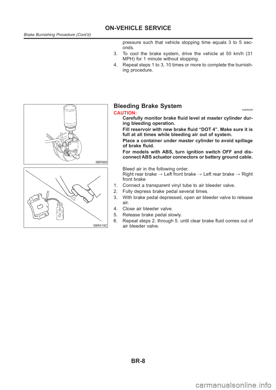
Bleeding Brake SystemNJBR0009CAUTION:
Carefully monitor brake fluid level at master cylinder dur-
ing bleeding operation.
Fill reservoir with new brake fluid “DOT 4”. Make sure it is
full at all times while bleeding air out of system.
Place a container under master cylinder to avoid spillage
of brake fluid.
For models with ABS, turn ignition switch OFF and dis-
connect ABS actuator connectors or battery ground cable.
SBR419C
Bleed air in the following order.
Right rear brake,Left front brake,Left rear brake,Right
front brake
1. Connect a transparent vinyl tube to air bleeder valve.
2. Fully depress brake pedal several times.
3. With brake pedal depressed, open air bleeder valve to release
air.
4. Close air bleeder valve.
5. Release brake pedal slowly.
6. Repeat steps 2. through 5. until clear brake fluid comes out of
air bleeder valve.
ON-VEHICLE SERVICE
Brake Burnishing Procedure (Cont’d)
BR-8
Page 2198 of 3189
RemovalNJBR0151
NBR351
1. Reservoir cap
2. Oil filter
3. Reservoir tank4. Seal
5. Cylinder body
6. Secondary piston assembly7. Primary piston assembly
8. Stopper cap
CAUTION:
Be careful not to splash brake fluid on painted areas; it may
cause paint damage. If brake fluid is splashed on painted
areas, wash it away with water immediately.
1. Connect a vinyl tube to air bleeder valve.
2. Drain brake fluid from each air bleeder valve, depressing brake
pedal to empty fluid from master cylinder.
3. Remove brake pipe flare nuts.
4. Remove master cylinder mounting nuts.
MASTER CYLINDER (NABCO)
Removal
BR-14
Page 2199 of 3189

SBR938A
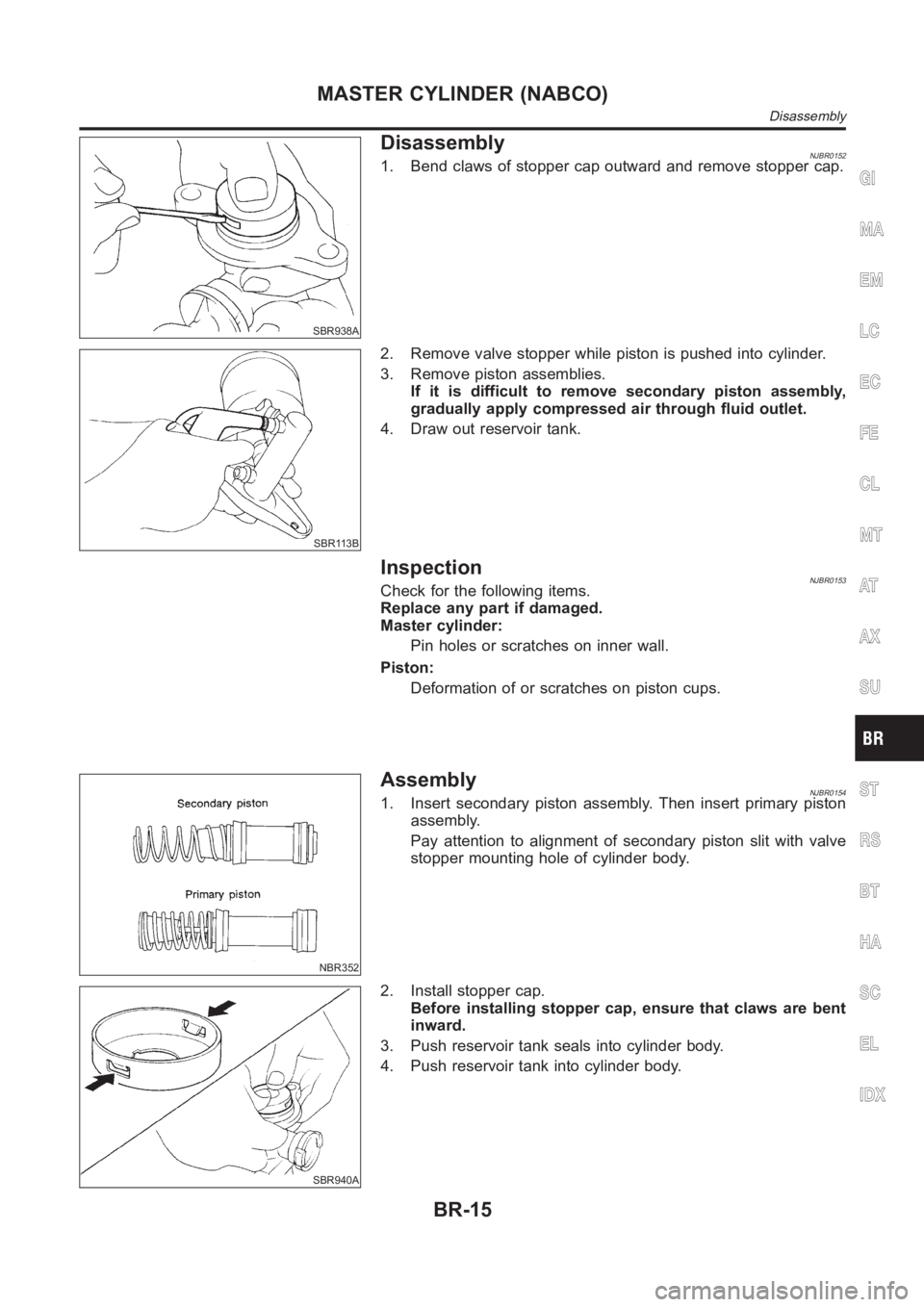
DisassemblyNJBR01521. Bend claws of stopper cap outward and remove stopper cap.
SBR113B
2. Remove valve stopper while piston is pushed into cylinder.
3. Remove piston assemblies.
If it is difficult to remove secondary piston assembly,
gradually apply compressed air through fluid outlet.
4. Draw out reservoir tank.
InspectionNJBR0153Check for the following items.
Replace any part if damaged.
Master cylinder:
Pin holes or scratches on inner wall.
Piston:
Deformation of or scratches on piston cups.
NBR352
AssemblyNJBR01541. Insert secondary piston assembly. Then insert primary piston
assembly.
Pay attention to alignment of secondary piston slit with valve
stopper mounting hole of cylinder body.
SBR940A
2. Install stopper cap.
Before installing stopper cap, ensure that claws are bent
inward.
3. Push reservoir tank seals into cylinder body.
4. Push reservoir tank into cylinder body.
GI
MA
EM
LC
EC
FE
CL
MT
AT
AX
SU
ST
RS
BT
HA
SC
EL
IDX
MASTER CYLINDER (NABCO)
Disassembly
BR-15
Page 2200 of 3189
SBR704C
InstallationNJBR0155CAUTION:
Refill with new brake fluid “DOT 4”.
Never reuse drained brake fluid.
1. Place master cylinder onto brake booster and secure mount-
ing nuts lightly.
2. Torque mounting nuts.
:12-15N·m(1.2-1.5kg-m,9-11ft-lb)
3. Fill up reservoir tank with new brake fluid.
4. Plug all ports on master cylinder with fingers to prevent air
suction while releasing brake pedal.
5. Have driver depress brake pedal slowly several times until no
air comes out of master cylinder.
6. Fit brake lines to master cylinder.
7. Tighten flare nuts.
: 15 - 18 N·m (1.5 - 1.8 kg-m, 11 - 13 ft-lb)
8. Bleed air from brake system. Refer to “Bleeding Brake
System”, BR-8.
MASTER CYLINDER (NABCO)
Installation
BR-16
Page 2201 of 3189
RemovalNJBR0117
SBR766E
1. Reservoir cap
2. Oil filter (ABS models only)
3. Reservoir tank
4. Seal5. Cylinder body
6. Elastic pin
7. Piston stopper pin8. Secondary piston assembly
9. Primary piston assembly
10. Circlip
CAUTION:
Be careful not to splash brake fluid on painted areas; it may
cause paint damage. If brake fluid is splashed on painted
areas, wash it away with water immediately.
1. Connect a vinyl tube to front caliper air bleeder valve.
2. Drain brake fluid from each front caliper air bleeder valve,
depressing brake pedal to empty fluid from master cylinder.
3. Remove brake pipe flare nuts.
4. Remove master cylinder mounting nuts.
SBR231E
DisassemblyNJBR01181. Drive out elastic pin from cylinder body.
2. Remove reservoir tank and seals.
GI
MA
EM
LC
EC
FE
CL
MT
AT
AX
SU
ST
RS
BT
HA
SC
EL
IDX
MASTER CYLINDER [BOSCH (NABCO)]
Removal
BR-17
Page 2202 of 3189
NBR353
3. Remove the circlip with suitable pliers while piston is pushed
into cylinder.
SBR232E
4. Remove piston stopper pin while piston is pushed into cylinder.
5. Remove piston assemblies.
If it is difficult to remove secondary piston assembly,
gradually apply compressed air through fluid outlet.
InspectionNJBR0119Check for the following items.
Replace any part if damaged.
Master cylinder:
Pin holes or scratches on inner wall.
Piston:
Deformation of or scratches on piston cups.
SBR233E
AssemblyNJBR01201. Insert secondary piston assembly. Then insert primary piston
assembly.
Pay attention to alignment of secondary piston slit with
valve stopper mounting hole of cylinder body.
SBR232E
2. Install piston stopper pin while piston is pushed into cylinder.
Then secure the primary and secondary piston assemblies
with circlip.
3. Push reservoir tank seals and reservoir tank into cylinder body.
4. Install elastic pin.
MASTER CYLINDER [BOSCH (NABCO)]
Disassembly (Cont’d)
BR-18
Page 2203 of 3189
SBR236E
InstallationNJBR0121CAUTION:
Refill with new brake fluid “DOT 4”.
Never reuse drained brake fluid.
1. Place master cylinder onto brake booster and secure mount-
ing nuts lightly.
2. Torque mounting nuts.
:13-15N·m(1.3-1.5kg-m,9-11ft-lb)
3. Fill up reservoir tank with new brake fluid.
4. Plug all ports on master cylinder with fingers to prevent air
suction while releasing brake pedal.
5. Have driver depress brake pedal slowly several times until no
air comes out of master cylinder.
6. Fit brake lines to master cylinder.
7. Tighten flare nuts.
: 15 - 18 N·m (1.5 - 1.8 kg-m, 11 - 13 ft-lb)
8. Bleed air from brake system.
GI
MA
EM
LC
EC
FE
CL
MT
AT
AX
SU
ST
RS
BT
HA
SC
EL
IDX
MASTER CYLINDER [BOSCH (NABCO)]
Installation
BR-19
Page 2212 of 3189

SBR976B
SBR932C
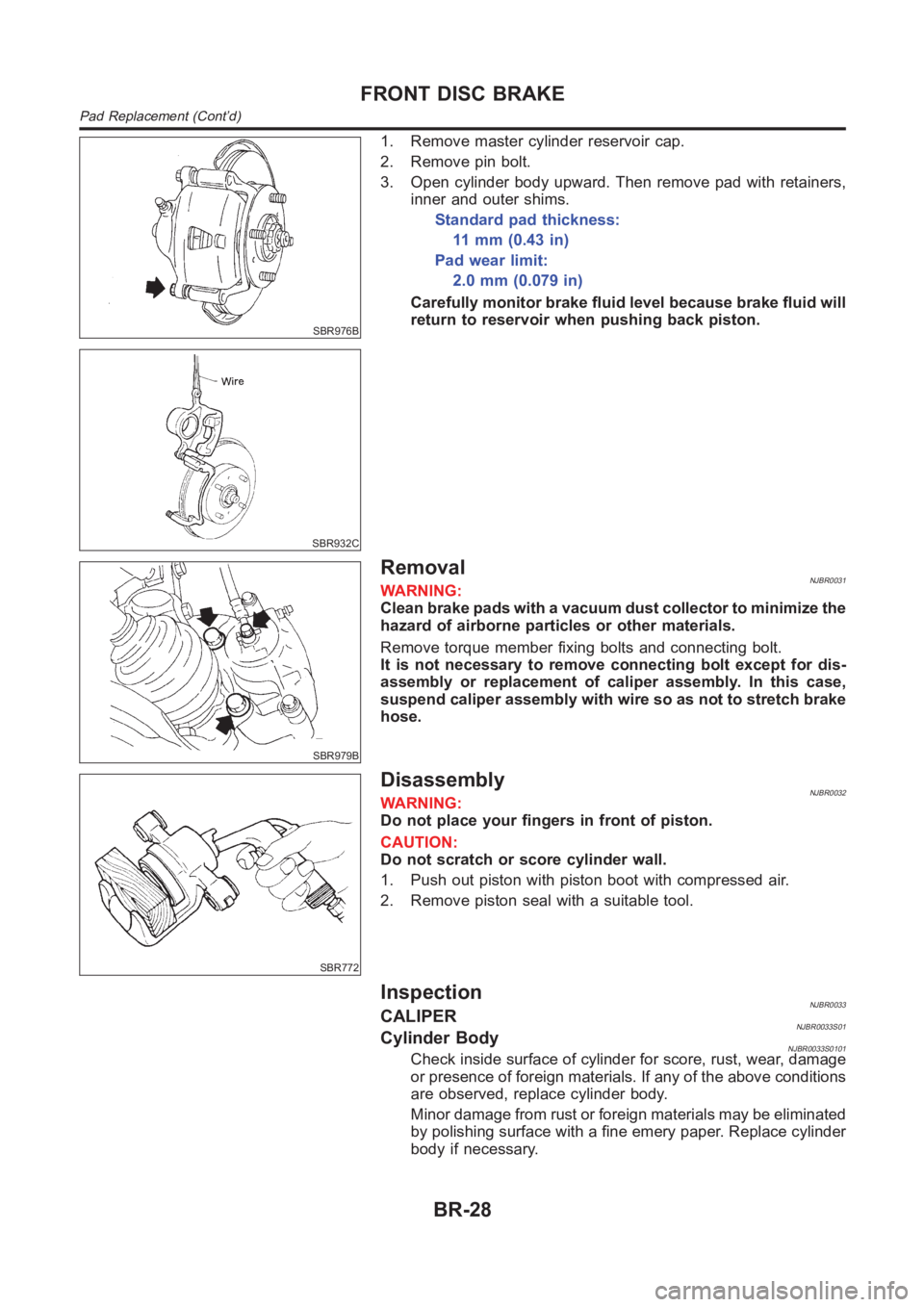
1. Remove master cylinder reservoir cap.
2. Remove pin bolt.
3. Open cylinder body upward. Then remove pad with retainers,
inner and outer shims.
Standard pad thickness:
11 m m ( 0 . 4 3 i n )
Pad wear limit:
2.0mm(0.079in)
Carefully monitor brake fluid level because brake fluid will
return to reservoir when pushing back piston.
SBR979B
RemovalNJBR0031WARNING:
Clean brake pads with a vacuum dust collector to minimize the
hazard of airborne particles or other materials.
Remove torque member fixing bolts and connecting bolt.
It is not necessary to remove connecting bolt except for dis-
assembly or replacement of caliper assembly. In this case,
suspend caliper assembly with wire so as not to stretch brake
hose.
SBR772
DisassemblyNJBR0032WARNING:
Do not place your fingers in front of piston.
CAUTION:
Do not scratch or score cylinder wall.
1. Push out piston with piston boot with compressed air.
2. Remove piston seal with a suitable tool.
InspectionNJBR0033CALIPERNJBR0033S01Cylinder BodyNJBR0033S0101Check inside surface of cylinder for score, rust, wear, damage
or presence of foreign materials. If any of the above conditions
are observed, replace cylinder body.
Minor damage from rust or foreign materials may be eliminated
by polishing surface with a fine emery paper. Replace cylinder
body if necessary.
FRONT DISC BRAKE
Pad Replacement (Cont’d)
BR-28