2003 NISSAN ALMERA N16 check engine
[x] Cancel search: check enginePage 120 of 3189
EM-42
[QG]
CAMSHAFT
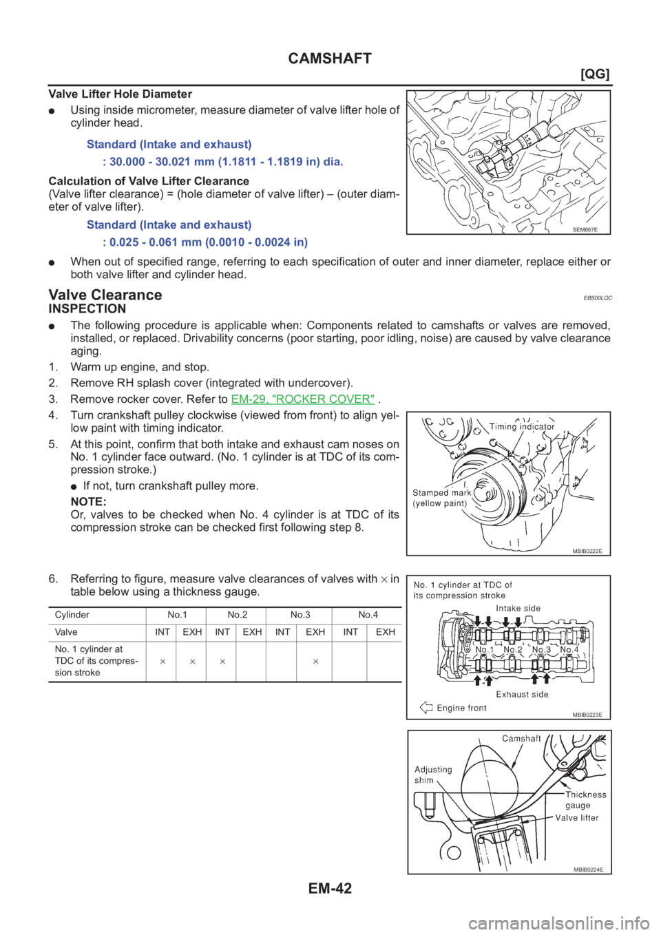
Valve Lifter Hole Diameter
●Using inside micrometer, measure diameter of valve lifter hole of
cylinder head.
Calculation of Valve Lifter Clearance
(Valve lifter clearance) = (hole diameter of valve lifter) – (outer diam-
eter of valve lifter).
●When out of specified range, referring to each specification of outer and inner diameter, replace either or
both valve lifter and cylinder head.
Valve ClearanceEBS00LQC
INSPECTION
●The following procedure is applicable when: Components related to camshafts or valves are removed,
installed, or replaced. Drivability concerns (poor starting, poor idling, noise) are caused by valve clearance
aging.
1. Warm up engine, and stop.
2. Remove RH splash cover (integrated with undercover).
3. Remove rocker cover. Refer to EM-29, "
ROCKER COVER" .
4. Turn crankshaft pulley clockwise (viewed from front) to align yel-
low paint with timing indicator.
5. At this point, confirm that both intake and exhaust cam noses on
No. 1 cylinder face outward. (No. 1 cylinder is at TDC of its com-
pression stroke.)
●If not, turn crankshaft pulley more.
NOTE:
Or, valves to be checked when No. 4 cylinder is at TDC of its
compression stroke can be checked first following step 8.
6. Referring to figure, measure valve clearances of valves with × in
table below using a thickness gauge.Standard (Intake and exhaust)
: 30.000 - 30.021 mm (1.1811 - 1.1819 in) dia.
Standard (Intake and exhaust)
: 0.025 - 0.061 mm (0.0010 - 0.0024 in)
SEM867E
MBIB0222E
Cylinder No.1 No.2 No.3 No.4
Valve INT EXH INT EXH INT EXH INT EXH
No. 1 cylinder at
TDC of its compres-
sion stroke××× ×
MBIB0223E
MBIB0224E
Page 122 of 3189
EM-44
[QG]
CAMSHAFT
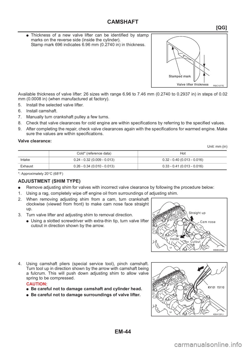
●Thickness of a new valve lifter can be identified by stamp
marks on the reverse side (inside the cylinder).
Stamp mark 696 indicates 6.96 mm (0.2740 in) in thickness.
Available thickness of valve lifter: 26 sizes with range 6.96 to 7.46 mm (0.2740 to 0.2937 in) in steps of 0.02
mm (0.0008 in) (when manufactured at factory).
5. Install the selected valve lifter.
6. Install camshaft.
7. Manually turn crankshaft pulley a few turns.
8. Check that valve clearances for cold engine are within specifications by referring to the specified values.
9. After completing the repair, check valve clearances again with the specifications for warmed engine. Make
sure the values are within specifications.
Valve clearance:
Unit: mm (in)
*: Approximately 20°C (68°F)
ADJUSTMENT (SHIM TYPE)
●Remove adjusting shim for valves with incorrect valve clearance by following the procedure below:
1. Using a rag, completely wipe off engine oil from surroundings of adjusting shim.
2. When removing adjusting shim from a cam, turn crankshaft
clockwise (viewed from front) to make cam nose face straight
up.
3. Turn valve lifter and adjusting shim to removal direction.
●Using a slotted screwdriver with extra-thin tip, turn valve lifter
cutout in direction shown by the arrow.
4. Using camshaft pliers (special service tool), pinch camshaft.
Turn tool up in direction shown by the arrow with camshaft being
a fulcrum. This will push down adjusting shim to allow valve
spring to be compressed.
CAUTION:
●Be careful not to damage camshaft and cylinder head.
●Be careful not to damage surroundings of valve lifter.
PBIC1077E
Cold* (reference data) Hot
Intake 0.24 - 0.32 (0.009 - 0.013) 0.32 - 0.40 (0.013 - 0.016)
Exhaust 0.26 - 0.34 (0.010 - 0.013) 0.33 - 0.41 (0.013 - 0.016)
MBIB0226E
KBIA1391J
Page 129 of 3189
TIMING CHAIN
EM-51
[QG]
C
D
E
F
G
H
I
J
K
L
MA
EM
30. Remove timing chain, timing chain slack guide and tension guide.
31. Remove crankshaft sprocket.
INSPECTION AFTER REMOVAL
Timing Chain
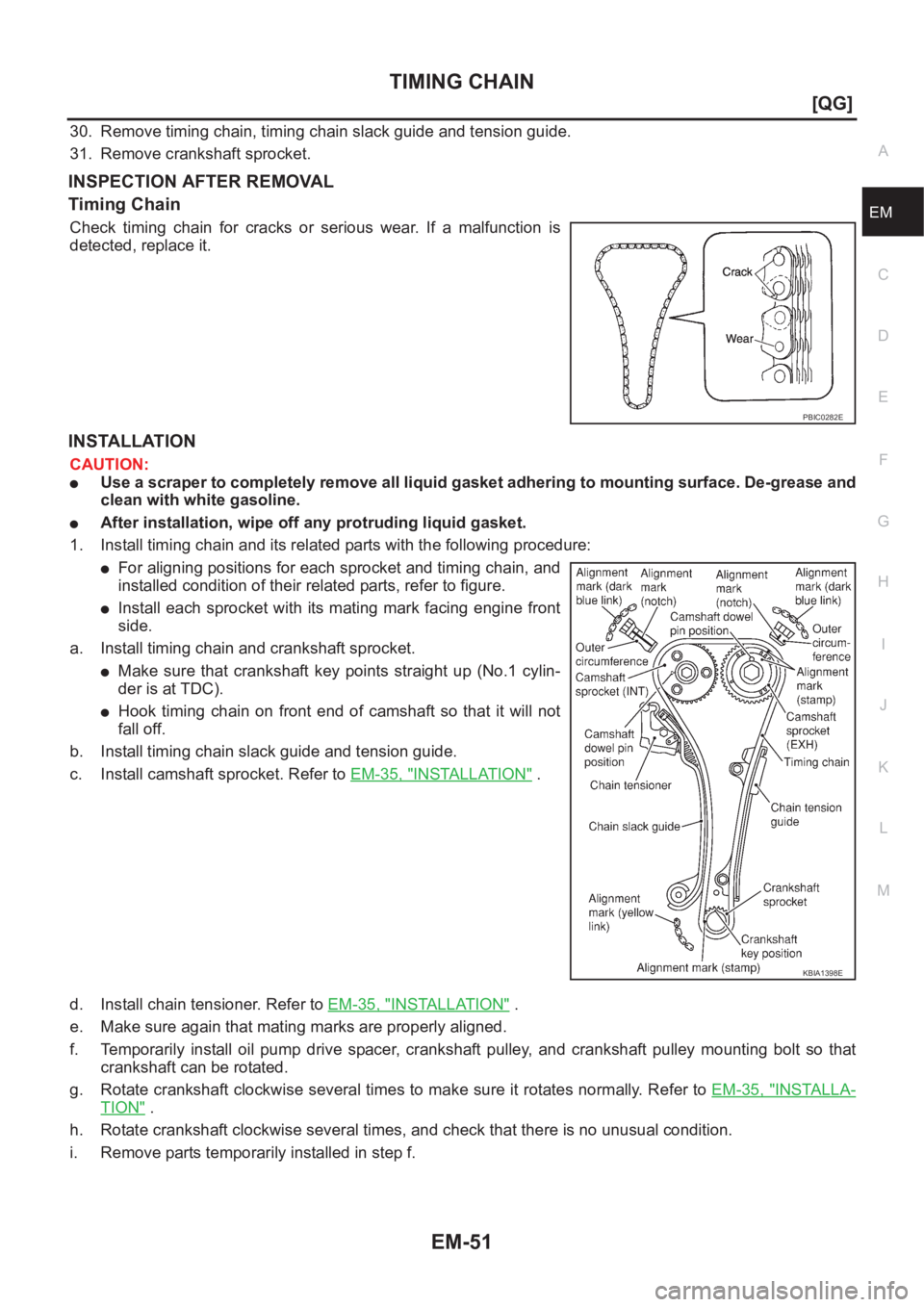
Check timing chain for cracks or serious wear. If a malfunction is
detected, replace it.
INSTALLATION
CAUTION:
●Use a scraper to completely remove all liquid gasket adhering to mounting surface. De-grease and
clean with white gasoline.
●After installation, wipe off any protruding liquid gasket.
1. Install timing chain and its related parts with the following procedure:
●For aligning positions for each sprocket and timing chain, and
installed condition of their related parts, refer to figure.
●Install each sprocket with its mating mark facing engine front
side.
a. Install timing chain and crankshaft sprocket.
●Make sure that crankshaft key points straight up (No.1 cylin-
der is at TDC).
●Hook timing chain on front end of camshaft so that it will not
fall off.
b. Install timing chain slack guide and tension guide.
c. Install camshaft sprocket. Refer to EM-35, "
INSTALLATION" .
d. Install chain tensioner. Refer to EM-35, "
INSTALLATION" .
e. Make sure again that mating marks are properly aligned.
f. Temporarily install oil pump drive spacer, crankshaft pulley, and crankshaft pulley mounting bolt so that
crankshaft can be rotated.
g. Rotate crankshaft clockwise several times to make sure it rotates normally. Refer to EM-35, "
INSTALLA-
TION" .
h. Rotate crankshaft clockwise several times, and check that there is no unusual condition.
i. Remove parts temporarily installed in step f.
PBIC0282E
KBIA1398E
Page 131 of 3189
TIMING CHAIN
EM-53
[QG]
C
D
E
F
G
H
I
J
K
L
MA
EM
h. Install front cover with mounting bolts temporarily so that front
cover will not move.
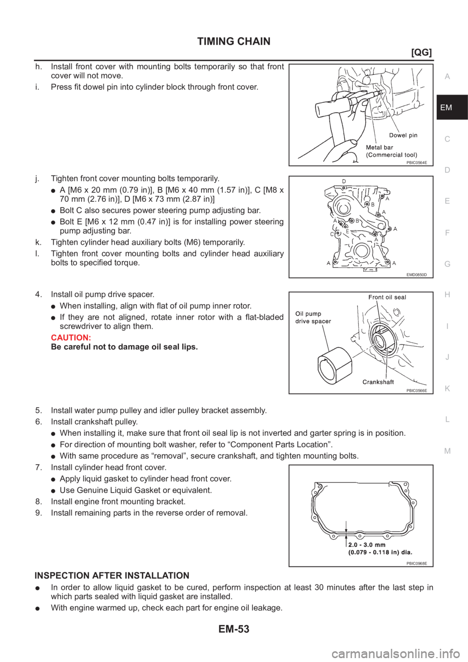
i. Press fit dowel pin into cylinder block through front cover.
j. Tighten front cover mounting bolts temporarily.
●A [M6 x 20 mm (0.79 in)], B [M6 x 40 mm (1.57 in)], C [M8 x
70 mm (2.76 in)], D [M6 x 73 mm (2.87 in)]
●Bolt C also secures power steering pump adjusting bar.
●Bolt E [M6 x 12 mm (0.47 in)] is for installing power steering
pump adjusting bar.
k. Tighten cylinder head auxiliary bolts (M6) temporarily.
l. Tighten front cover mounting bolts and cylinder head auxiliary
bolts to specified torque.
4. Install oil pump drive spacer.
●When installing, align with flat of oil pump inner rotor.
●If they are not aligned, rotate inner rotor with a flat-bladed
screwdriver to align them.
CAUTION:
Be careful not to damage oil seal lips.
5. Install water pump pulley and idler pulley bracket assembly.
6. Install crankshaft pulley.
●When installing it, make sure that front oil seal lip is not inverted and garter spring is in position.
●For direction of mounting bolt washer, refer to “Component Parts Location”.
●With same procedure as “removal”, secure crankshaft, and tighten mounting bolts.
7. Install cylinder head front cover.
●Apply liquid gasket to cylinder head front cover.
●Use Genuine Liquid Gasket or equivalent.
8. Install engine front mounting bracket.
9. Install remaining parts in the reverse order of removal.
INSPECTION AFTER INSTALLATION
●In order to allow liquid gasket to be cured, perform inspection at least 30 minutes after the last step in
which parts sealed with liquid gasket are installed.
●With engine warmed up, check each part for engine oil leakage.
PBIC0564E
EMD0850D
PBIC0566E
PBIC0968E
Page 135 of 3189
CYLINDER HEAD
EM-57
[QG]
C
D
E
F
G
H
I
J
K
L
MA
EM
CYLINDER HEADPFP:11041
On-Vehicle ServiceEBS00LQH
CHECKING COMPRESSION PRESSURE
1. Warm up engine thoroughly. Then, stop it.
2. Release fuel pressure. Refer to EC-34, "
FUEL PRESSURE RELEASE" (WITH EURO-OBD), EC-427,
"FUEL PRESSURE RELEASE" (WITHOUT EURO-OBD).
3. Remove ignition coil and spark plug from each cylinder.
Refer to IGNITION COIL EM-24, "
Removal and Installation" and SPARK PLUG EM-25, "Removal and
Installation" .
4. Connect engine tachometer (not required in use of CONSULT-II).
5. Disconnect fuel injector harness connector so that no fuel is injected.
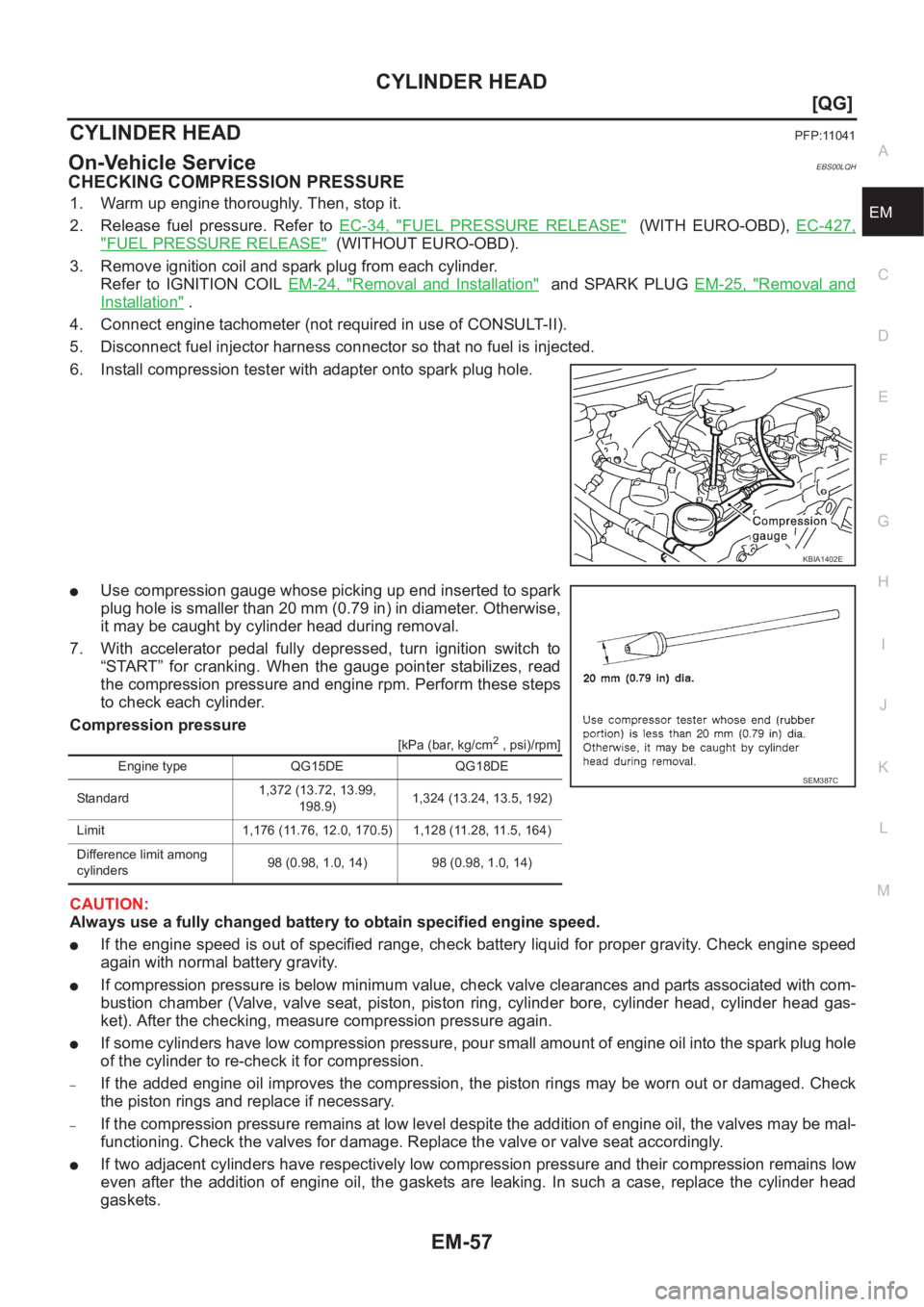
6. Install compression tester with adapter onto spark plug hole.
●Use compression gauge whose picking up end inserted to spark
plug hole is smaller than 20 mm (0.79 in) in diameter. Otherwise,
it may be caught by cylinder head during removal.
7. With accelerator pedal fully depressed, turn ignition switch to
“START” for cranking. When the gauge pointer stabilizes, read
the compression pressure and engine rpm. Perform these steps
to check each cylinder.
Compression pressure
[kPa (bar, kg/cm2 , psi)/rpm]
CAUTION:
Always use a fully changed battery to obtain specified engine speed.
●If the engine speed is out of specified range, check battery liquid for proper gravity. Check engine speed
again with normal battery gravity.
●If compression pressure is below minimum value, check valve clearances and parts associated with com-
bustion chamber (Valve, valve seat, piston, piston ring, cylinder bore, cylinder head, cylinder head gas-
ket). After the checking, measure compression pressure again.
●If some cylinders have low compression pressure, pour small amount of engine oil into the spark plug hole
of the cylinder to re-check it for compression.
–If the added engine oil improves the compression, the piston rings may be worn out or damaged. Check
the piston rings and replace if necessary.
–If the compression pressure remains at low level despite the addition of engine oil, the valves may be mal-
functioning. Check the valves for damage. Replace the valve or valve seat accordingly.
●If two adjacent cylinders have respectively low compression pressure and their compression remains low
even after the addition of engine oil, the gaskets are leaking. In such a case, replace the cylinder head
gaskets.
KBIA1402E
Engine type QG15DE QG18DE
Standard1,372 (13.72, 13.99,
198.9)1,324 (13.24, 13.5, 192)
Limit 1,176 (11.76, 12.0, 170.5) 1,128 (11.28, 11.5, 164)
Difference limit among
cylinders98 (0.98, 1.0, 14) 98 (0.98, 1.0, 14)SEM387C
Page 137 of 3189
CYLINDER HEAD
EM-59
[QG]
C
D
E
F
G
H
I
J
K
L
MA
EM
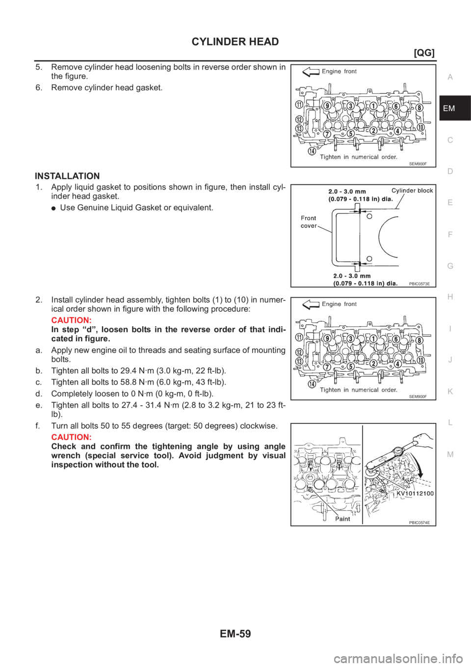
5. Remove cylinder head loosening bolts in reverse order shown in
the figure.
6. Remove cylinder head gasket.
INSTALLATION
1. Apply liquid gasket to positions shown in figure, then install cyl-
inder head gasket.
●Use Genuine Liquid Gasket or equivalent.
2. Install cylinder head assembly, tighten bolts (1) to (10) in numer-
ical order shown in figure with the following procedure:
CAUTION:
In step “d”, loosen bolts in the reverse order of that indi-
cated in figure.
a. Apply new engine oil to threads and seating surface of mounting
bolts.
b. Tighten all bolts to 29.4 N·m (3.0 kg-m, 22 ft-lb).
c. Tighten all bolts to 58.8 N·m (6.0 kg-m, 43 ft-lb).
d. Completely loosen to 0 N·m (0 kg-m, 0 ft-lb).
e. Tighten all bolts to 27.4 - 31.4 N·m (2.8 to 3.2 kg-m, 21 to 23 ft-
lb).
f. Turn all bolts 50 to 55 degrees (target: 50 degrees) clockwise.
CAUTION:
Check and confirm the tightening angle by using angle
wrench (special service tool). Avoid judgment by visual
inspection without the tool.
SEM900F
PBIC0573E
SEM900F
PBIC0574E
Page 140 of 3189
EM-62
[QG]
CYLINDER HEAD
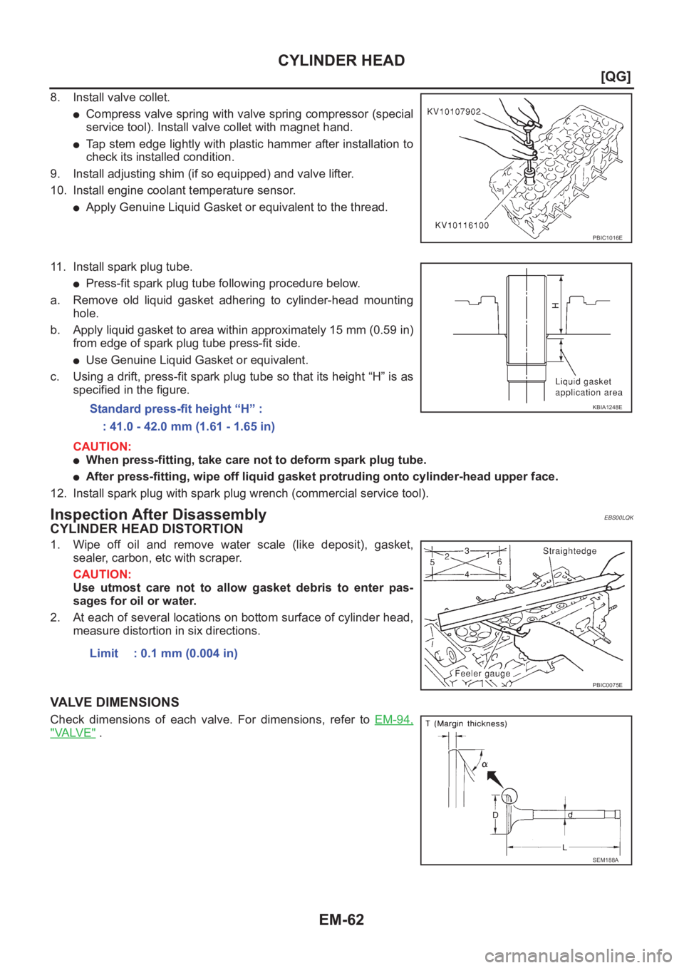
8. Install valve collet.
●Compress valve spring with valve spring compressor (special
service tool). Install valve collet with magnet hand.
●Tap stem edge lightly with plastic hammer after installation to
check its installed condition.
9. Install adjusting shim (if so equipped) and valve lifter.
10. Install engine coolant temperature sensor.
●Apply Genuine Liquid Gasket or equivalent to the thread.
11. Install spark plug tube.
●Press-fit spark plug tube following procedure below.
a. Remove old liquid gasket adhering to cylinder-head mounting
hole.
b. Apply liquid gasket to area within approximately 15 mm (0.59 in)
from edge of spark plug tube press-fit side.
●Use Genuine Liquid Gasket or equivalent.
c. Using a drift, press-fit spark plug tube so that its height “H” is as
specified in the figure.
CAUTION:
●When press-fitting, take care not to deform spark plug tube.
●After press-fitting, wipe off liquid gasket protruding onto cylinder-head upper face.
12. Install spark plug with spark plug wrench (commercial service tool).
Inspection After DisassemblyEBS00LQK
CYLINDER HEAD DISTORTION
1. Wipe off oil and remove water scale (like deposit), gasket,
sealer, carbon, etc with scraper.
CAUTION:
Use utmost care not to allow gasket debris to enter pas-
sages for oil or water.
2. At each of several locations on bottom surface of cylinder head,
measure distortion in six directions.
VALVE DIMENSIONS
Check dimensions of each valve. For dimensions, refer to EM-94,
"VA LV E" .
PBIC1016E
Standard press-fit height “H” :
: 41.0 - 42.0 mm (1.61 - 1.65 in)KBIA1248E
Limit : 0.1 mm (0.004 in)
PBIC0075E
SEM188A
Page 153 of 3189
CYLINDER BLOCK
EM-75
[QG]
C
D
E
F
G
H
I
J
K
L
MA
EM
17. Remove crankshaft.
CAUTION:
●When placing crankshaft on ground, be careful not to
damage signal plate.
●Never remove signal plate unless it is necessary.
NOTE:
If it is removed, positioning dowel pin (dowel pins for crankshaft
and signal plate are specified as a single set) must be rein-
stalled.
18. Remove main bearing and thrust bearing from cylinder block and main bearing cap.
CAUTION:
Check mounting positions, and store them without mixing them up.
19. Remove baffle plate.
ASSEMBLY
1. Blow air sufficiently through engine coolant passage of cylinder block, oil passage, crank case and cylin-
der bore to remove foreign objects.
2. Install oil jet for timing chain lubrication.
●Face its flat surface upward, and push it as far as it will go.
3. Install baffle plate.
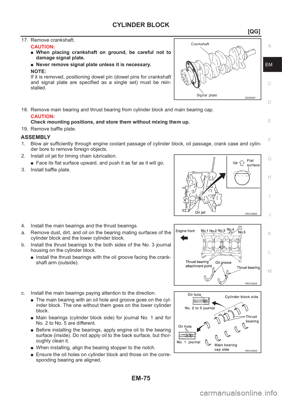
4. Install the main bearings and the thrust bearings.
a. Remove dust, dirt, and oil on the bearing mating surfaces of the
cylinder block and the lower cylinder block.
b. Install the thrust bearings to the both sides of the No. 3 journal
housing on the cylinder block.
●Install the thrust bearings with the oil groove facing the crank-
shaft arm (outside).
c. Install the main bearings paying attention to the direction.
●The main bearing with an oil hole and groove goes on the cyl-
inder block. The one without them goes on the lower cylinder
block.
●Main bearings (cylinder block side) for journal No. 1 and for
No. 2 to No. 5 are different.
●Before installing the bearings, apply engine oil to the bearing
surface (inside). Do not apply oil to the back surface, but thor-
oughly clean it.
●When installing, align the bearing stopper to the notch.
●Ensure the oil holes on cylinder block and those on the corre-
sponding bearing are aligned.
SEM928F
PBIC0588E
PBIC0264E
PBIC0590E