Page 1255 of 3189

3 CHECK EGR VOLUME CONTROL VALVE POWER SUPPLY CIRCUIT-II
1. Turn ignition switch “OFF”.
2. Disconnect ECM relay. (For ECM relay location, refer to “Engine ControlComponent Parts Location”.)
3. Check harness continuity between ECM relay terminal 5 and EGR volume control valve terminals 2 and 5. Refer to
Wiring Diagram.
Continuity should exist.
OK or NG
OK GO TO 5.
NG GO TO 4.
4 DETECT MALFUNCTIONING PART
Check the following.
Harness connectors E174, M159 (LHD models)
Harness connectors E251, M182 (RHD models)
Harness connectors M63, F102
Harness for open or short between ECM relay and EGR volume control valve
Repair open circuit or short to power in harness or connectors.
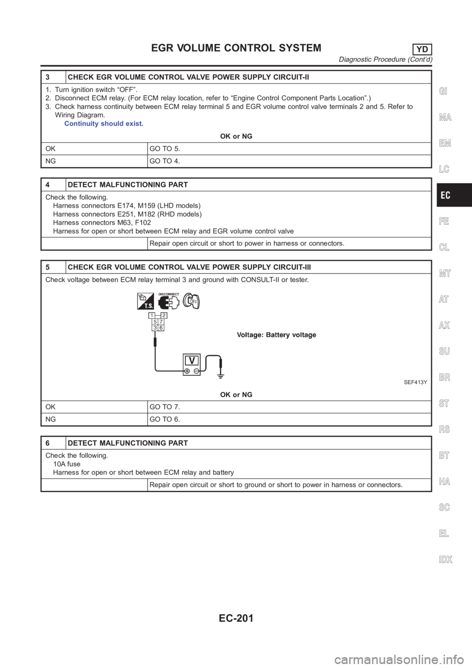
5 CHECK EGR VOLUME CONTROL VALVE POWER SUPPLY CIRCUIT-III
Check voltage between ECM relay terminal 3 and ground with CONSULT-II or tester.
SEF413Y
OK or NG
OK GO TO 7.
NG GO TO 6.
6 DETECT MALFUNCTIONING PART
Check the following.
10A fuse
Harness for open or short between ECM relay and battery
Repair open circuit or short to ground or short to power in harness or connectors.
GI
MA
EM
LC
FE
CL
MT
AT
AX
SU
BR
ST
RS
BT
HA
SC
EL
IDX
EGR VOLUME CONTROL SYSTEMYD
Diagnostic Procedure (Cont’d)
EC-201
Page 1260 of 3189

Diagnostic ProcedureNJEC0770
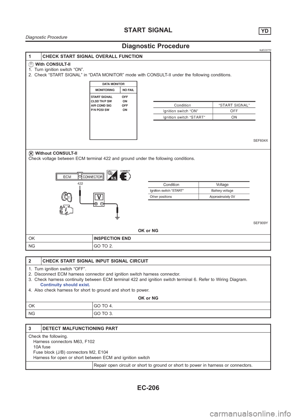
1 CHECK START SIGNAL OVERALL FUNCTION
With CONSULT-II
1. Turn ignition switch “ON”.
2. Check “START SIGNAL” in “DATA MONITOR” mode with CONSULT-II under the following conditions.
SEF604X
Without CONSULT-II
Check voltage between ECM terminal 422 and ground under the following conditions.
SEF909Y
OK or NG
OKINSPECTION END
NG GO TO 2.
2 CHECK START SIGNAL INPUT SIGNAL CIRCUIT
1. Turn ignition switch “OFF”.
2. Disconnect ECM harness connector and ignition switch harness connector.
3. Check harness continuity between ECM terminal 422 and ignition switch terminal 6. Refer to Wiring Diagram.
Continuity should exist.
4. Also check harness for short to ground and short to power.
OK or NG
OK GO TO 4.
NG GO TO 3.
3 DETECT MALFUNCTIONING PART
Check the following.
Harness connectors M63, F102
10A fuse
Fuse block (J/B) connectors M2, E104
Harness for open or short between ECM and ignition switch
Repair open circuit or short to ground or short to power in harness or connectors.
START SIGNALYD
Diagnostic Procedure
EC-206
Page 1798 of 3189
AT-342
[ALL]
MAIN POWER SUPPLY AND GROUND CIRCUIT
3. DETECT MALFUNCTIONING ITEM
Check the following items:
●Harness for short or open between ignition switch and TCM terminals 10, 19 and 28
●Fuse
●Ignition switch
Refer to EL-11,"POWER SUPPLY ROUTING".
OK or NG
OK >> GO TO 4
NG >> Repair or replace damaged parts.
4. CHECK TCM GROUND CIRCUIT
1. Turn ignition switch to OFF position.
2. Disconnect TCM harness connector.
3. Check continuity between TCM terminals 25, 48 and ground. Refer to AT- 3 4 0 , "
Wiring Diagram — AT —
MAIN" .
If OK, check harness for short to ground and short to power.
OK or NG
OK >>INSPECTION END
NG >> Repair open circuit or short to ground or short to power in harness or connectors. Continuity should exist.
Page 2636 of 3189
KEY SWITCH (INSERT) CHECK=NJEL0505S11
1 CHECK KEY SWITCH INPUT SIGNAL
Check voltage between time control unit terminal 22 and ground.
SEL433X
Refer to wiring diagram in EL-306.
OK or NG
OK Key switch is OK.
NG GO TO 2.
2 CHECK KEY SWITCH (INSERT)
Check continuity between key switch terminals 1 and 2.
YEL802C
OK or NG
OKCheck the following.
10A fuse [No. 12, located in fuse block (J/B)]
Harness for open or short between key switch and fuse
Harness for open or short between time control unit and key switch
NG Replace key switch.
POWER DOOR LOCK
Trouble Diagnoses/YD Engine Models with Common Rail and K9K Engine Models(Cont’d)
EL-300
Page 2686 of 3189
KEY SWITCH (INSERT) CHECK=NJEL0477S10
1 CHECK KEY SWITCH INPUT SIGNAL
Check voltage between time control unit terminal 22 and ground.
SEL433X
Refer to wiring diagram in EL-306.
OK or NG
OK Key switch is OK.
NG GO TO 2.
2 CHECK KEY SWITCH (INSERT)
Check continuity between key switch terminals 1 and 2.
YEL802C
OK or NG
OKCheck the following.
10A fuse [No. 12, located in fuse block (J/B)]
Harness for open or short between key switch and fuse
Harness for open or short between time control unit and key switch
NG Replace key switch.
POWER DOOR LOCK — SUPER LOCK —
Trouble Diagnoses/YD Engine Models without Common Rail and K9K Engine Models (Cont’d)
EL-350
Page 2698 of 3189
POWER SUPPLY AND GROUND CIRCUIT CHECK=NJEL0482S03
1 CHECK MAIN POWER SUPPLY CIRCUIT FOR TIME CONTROL UNIT
1. Disconnect time control unit harness connector.
2. Check voltage between time control unit harness connector terminal 9 and ground.
SEL487X
Refer to wiring diagram in EL-353.
OK or NG
OK GO TO 2.
NGCheck the following.
15A fuse [No. 5, located in fuse block (J/B)]
Harness for open or short between time control unit and fuse
2 CHECK GROUND CIRCUIT FOR TIME CONTROL UNIT
Check continuity between time control unit harness connector terminal 16and ground.
SEL448X
Refer to wiring diagram in EL-353.
OK or NG
OK Power supply and ground circuits are OK.
NG Check ground harness.
MULTI-REMOTE CONTROL SYSTEM
Trouble Diagnoses/YD Engine Models without Common Rail and K9K Engine Models (Cont’d)
EL-362
Page 2731 of 3189

SYMPTOMDisplayed “SELF-DIAG
RESULTS” on CON-
SULT-II screen.DIAGNOSTIC PROCE-
DURE
(Reference page)SYSTEM
(Malfunctioning part or
mode)REFERENCE PART
NO. OF ILLUSTRATION
ON SYSTEM DIAGRAM
Security indicator
lighting up*
Engine cannot be
started
CHAIN OF IMMU-KEYPROCEDURE 4
(EL-400, “Diagnostic
Procedure 4”)Malfunction of key ID
chipE5
Communication line
between ANT/ AMP and
IMMU:
Open circuit or short
circuit of battery voltage
line or ground lineE1
E2
Open circuit in power
source line of ANT/ AMP
circuitE3
Open circuit in ground
line of ANT/ AMP circuitE4
Antenna amp. E6
Dongle unit G
IMMU A
ID DISCORD, IMM-ECMPROCEDURE 5
(EL-403, “Diagnostic
Procedure 5”)System initialization has
not yet been completed.F
ECM B
LOCK MODEPROCEDURE 7
(EL-406, “Diagnostic
Procedure 7”)LOCK MODE D
Security indicator light-
ing up*DON’T ERASE
BEFORE CHECKING
ENG DIAGWORK FLOW
(EL-393, “Work Flow”)Engine trouble data and
NATS trouble data have
been detected in ECM—
*: When NATS detects trouble, the security indicator lights up while ignition key is in the “ON” position.
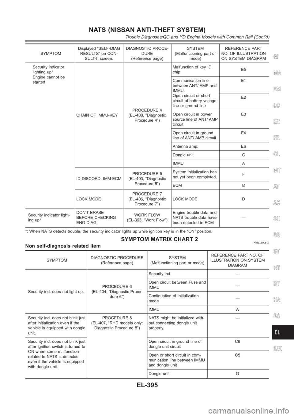
SYMPTOM MATRIX CHART 2NJEL0590S03Non self-diagnosis related item
SYMPTOMDIAGNOSTIC PROCEDURE
(Reference page)SYSTEM
(Malfunctioning part or mode)REFERENCE PART NO. OF
ILLUSTRATION ON SYSTEM
DIAGRAM
Security ind. does not light up.PROCEDURE 6
(EL-404, “Diagnostic Proce-
dure 6”)Security ind. —
Open circuit between Fuse and
IMMU—
Continuation of initialization
mode—
IMMU A
Security ind. does not blink just
after initialization even if the
vehicle is equipped with dongle
unit.PROCEDURE 8
(EL-407, “RHD models only:
Diagnostic Procedure 8”)NATS might be initialized with-
out connecting dongle unit
properly.—
Security ind. does not blink just
after ignition switch is turned to
ON when some malfunction
related to NATS is detected
even if the vehicle is equipped
with dongle unit.Open circuit in ground line of
dongle unit circuitC6
Open or short circuit in com-
munication line between IMMU
and dongle unitC5
Dongle unit G
GI
MA
EM
LC
EC
FE
CL
MT
AT
AX
SU
BR
ST
RS
BT
HA
SC
IDX
NATS (NISSAN ANTI-THEFT SYSTEM)
Trouble Diagnoses/QG and YD Engine Models with Common Rail (Cont’d)
EL-395
Page 2750 of 3189

SYMPTOMDisplayed “SELF-DIAG
RESULTS” on CON-
SULT-II screen.DIAGNOSTIC PROCE-
DURE
(Reference page)SYSTEM
(Malfunctioning part or
mode)REFERENCE PART
NO. OF ILLUSTRATION
ON SYSTEM DIAGRAM
MIL staying ON
Security indicator
lighting up*DON’T ERASE
BEFORE CHECKING
ENG DIAGWORK FLOW
(EL-412)Engine trouble data and
NATS trouble data have
been detected in ECM—
*: When NATS detects trouble, the security indicator lights up while ignition key is in the “ON” position.
*: When the vehicle is equipped with a dongle unit (RHD models for Europe), the security indicator blinks 6 times just after the ignition
switch is turned to ON. Then the security indicator lights up while the ignition key is in the “ON” position.
SYMPTOM MATRIX CHART 2NJEL0411S03(Non self-diagnosis related item)
SYMPTOMDIAGNOSTIC PROCEDURE
(Reference page)SYSTEM
(Malfunctioning part or mode)REFERENCE PART NO. OF
ILLUSTRATION ON SYSTEM
DIAGRAM
Security ind. does not light up.PROCEDURE 6
(EL-424)Security ind. —
Open circuit between Fuse and
IMMU—
Continuation of initialization
mode—
IMMU A
Security ind. does not blink just
after initialization even if the
vehicle is equipped with dongle
unit.
PROCEDURE 8
(EL-428)NATS might be initialized with-
out connecting dongle unit
properly.—
Open circuit in ground line of
dongle unit circuitC6
Security ind. does not blink just
after ignition switch is turned to
ON when some malfunction
related to NATS is detected
even if the vehicle is equipped
with dongle unit.Open or short circuit in com-
munication line between IMMU
and dongle unitC5
Dongle unit G
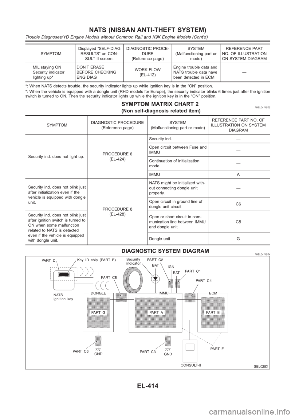
DIAGNOSTIC SYSTEM DIAGRAMNJEL0411S04
SEL028X
NATS (NISSAN ANTI-THEFT SYSTEM)
Trouble Diagnoses/YD Engine Models without Common Rail and K9K Engine Models (Cont’d)
EL-414