2003 NISSAN ALMERA N16 TEMP GAUGE
[x] Cancel search: TEMP GAUGEPage 2457 of 3189
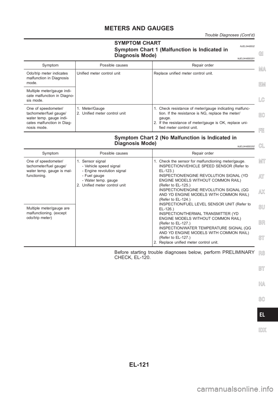
SYMPTOM CHARTNJEL0448S02Symptom Chart 1 (Malfunction is Indicated in
Diagnosis Mode)
NJEL0448S0201
Symptom Possible causes Repair order
Odo/trip meter indicates
malfunction in Diagnosis
mode.Unified meter control unit Replace unified meter control unit.
Multiple meter/gauge indi-
cate malfunction in Diagno-
sis mode.
One of speedometer/
tachometer/fuel gauge/
water temp. gauge indi-
cates malfunction in Diag-
nosis mode.1. Meter/Gauge
2. Unified meter control unit1. Check resistance of meter/gauge indicating malfunc-
tion. If the resistance is NG, replace the meter/
gauge.
2. If the resistance of meter/gauge is OK, replace uni-
fied meter control unit.
Symptom Chart 2 (No Malfunction is Indicated in
Diagnosis Mode)
NJEL0448S0202
Symptom Possible causes Repair order
One of speedometer/
tachometer/fuel gauge/
water temp. gauge is mal-
functioning.1. Sensor signal
- Vehicle speed signal
- Engine revolution signal
- Fuel gauge
- Water temp. gauge
2. Unified meter control unit1. Check the sensor for malfunctioning meter/gauge.
INSPECTION/VEHICLE SPEED SENSOR (Refer to
EL-123.)
INSPECTION/ENGINE REVOLUTION SIGNAL (YD
ENGINE MODELS WITHOUT COMMON RAIL)
(Refer to EL-125.)
INSPECTION/ENGINE REVOLUTION SIGNAL (QG
AND YD ENGINE MODELS WITH COMMON RAIL)
(Refer to EL-124.)
INSPECTION/FUEL LEVEL SENSOR UNIT (Refer to
EL-126.)
INSPECTION/THERMAL TRANSMITTER (YD
ENGINE MODELS WITHOUT COMMON RAIL)
(Refer to EL-127.)
INSPECTION/WATER TEMPERATURE SIGNAL (QG
AND YD ENGINE MODELS WITH COMMON RAIL)
(Refer to EL-127.)
2. Replace unified meter control unit. Multiple meter/gauge are
malfunctioning. (except
odo/trip meter)
Before starting trouble diagnoses below, perform PRELIMINARY
CHECK, EL-120.
GI
MA
EM
LC
EC
FE
CL
MT
AT
AX
SU
BR
ST
RS
BT
HA
SC
IDX
METERS AND GAUGES
Trouble Diagnoses (Cont’d)
EL-121
Page 2463 of 3189
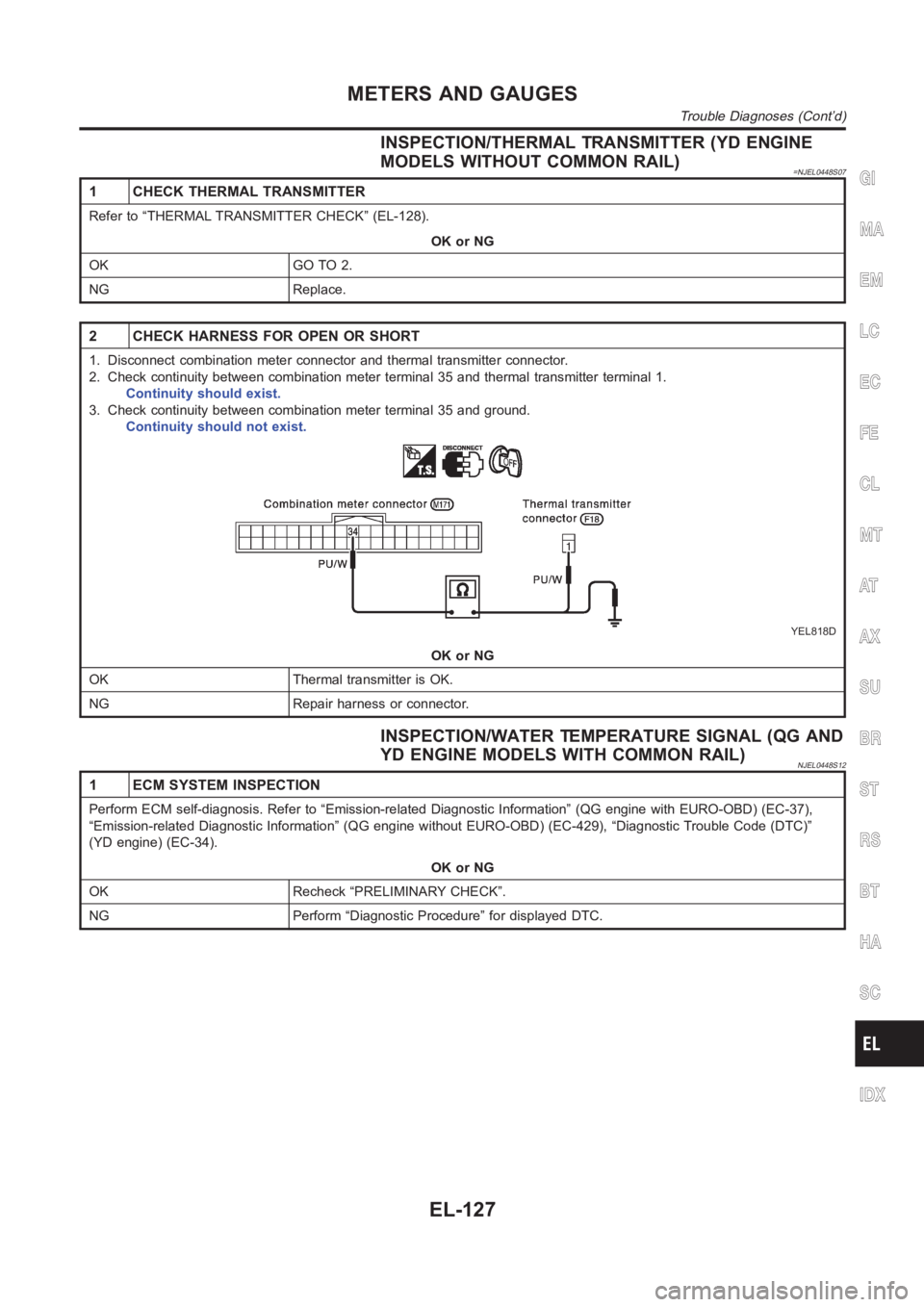
INSPECTION/THERMAL TRANSMITTER (YD ENGINE
MODELS WITHOUT COMMON RAIL)
=NJEL0448S07
1 CHECK THERMAL TRANSMITTER
Refer to “THERMAL TRANSMITTER CHECK” (EL-128).
OK or NG
OK GO TO 2.
NG Replace.
2 CHECK HARNESS FOR OPEN OR SHORT
1. Disconnect combination meter connector and thermal transmitter connector.
2. Check continuity between combination meter terminal 35 and thermal transmitter terminal 1.
Continuity should exist.
3. Check continuity between combination meter terminal 35 and ground.
Continuity should not exist.
YEL818D
OK or NG
OK Thermal transmitter is OK.
NG Repair harness or connector.
INSPECTION/WATER TEMPERATURE SIGNAL (QG AND
YD ENGINE MODELS WITH COMMON RAIL)
NJEL0448S12
1 ECM SYSTEM INSPECTION
Perform ECM self-diagnosis. Refer to “Emission-related Diagnostic Information” (QG engine with EURO-OBD) (EC-37),
“Emission-related Diagnostic Information” (QG engine without EURO-OBD) (EC-429), “Diagnostic Trouble Code (DTC)”
(YD engine) (EC-34).
OK or NG
OK Recheck “PRELIMINARY CHECK”.
NG Perform “Diagnostic Procedure” for displayed DTC.
GI
MA
EM
LC
EC
FE
CL
MT
AT
AX
SU
BR
ST
RS
BT
HA
SC
IDX
METERS AND GAUGES
Trouble Diagnoses (Cont’d)
EL-127
Page 2464 of 3189
SEL498X
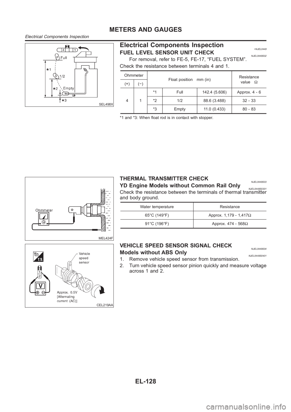
Electrical Components Inspection=NJEL0449FUEL LEVEL SENSOR UNIT CHECKNJEL0449S02For removal, refer to FE-5, FE-17, “FUEL SYSTEM”.
Check the resistance between terminals 4 and 1.
Ohmmeter
Float position mm (in)Resistance
valueΩ
(+) (−)
41*1 Full 142.4 (5.606) Approx. 4 - 6
*2 1/2 88.6 (3.488) 32 - 33
*3 Empty 11.0 (0.433) 80 - 83
*1 and *3: When float rod is in contact with stopper.
MEL424F
THERMAL TRANSMITTER CHECKNJEL0449S03YD Engine Models without Common Rail OnlyNJEL0449S0301Check the resistance between the terminals of thermal transmitter
and body ground.
Water temperature Resistance
65°C (149°F) Approx. 1,179 - 1,417Ω
91°C (196°F) Approx. 474 - 568Ω
CEL219AA
VEHICLE SPEED SENSOR SIGNAL CHECKNJEL0449S04Models without ABS OnlyNJEL0449S04011. Remove vehicle speed sensor from transmission.
2. Turn vehicle speed sensor pinion quickly and measure voltage
across 1 and 2.
METERS AND GAUGES
Electrical Components Inspection
EL-128
Page 2935 of 3189
NJEL0311
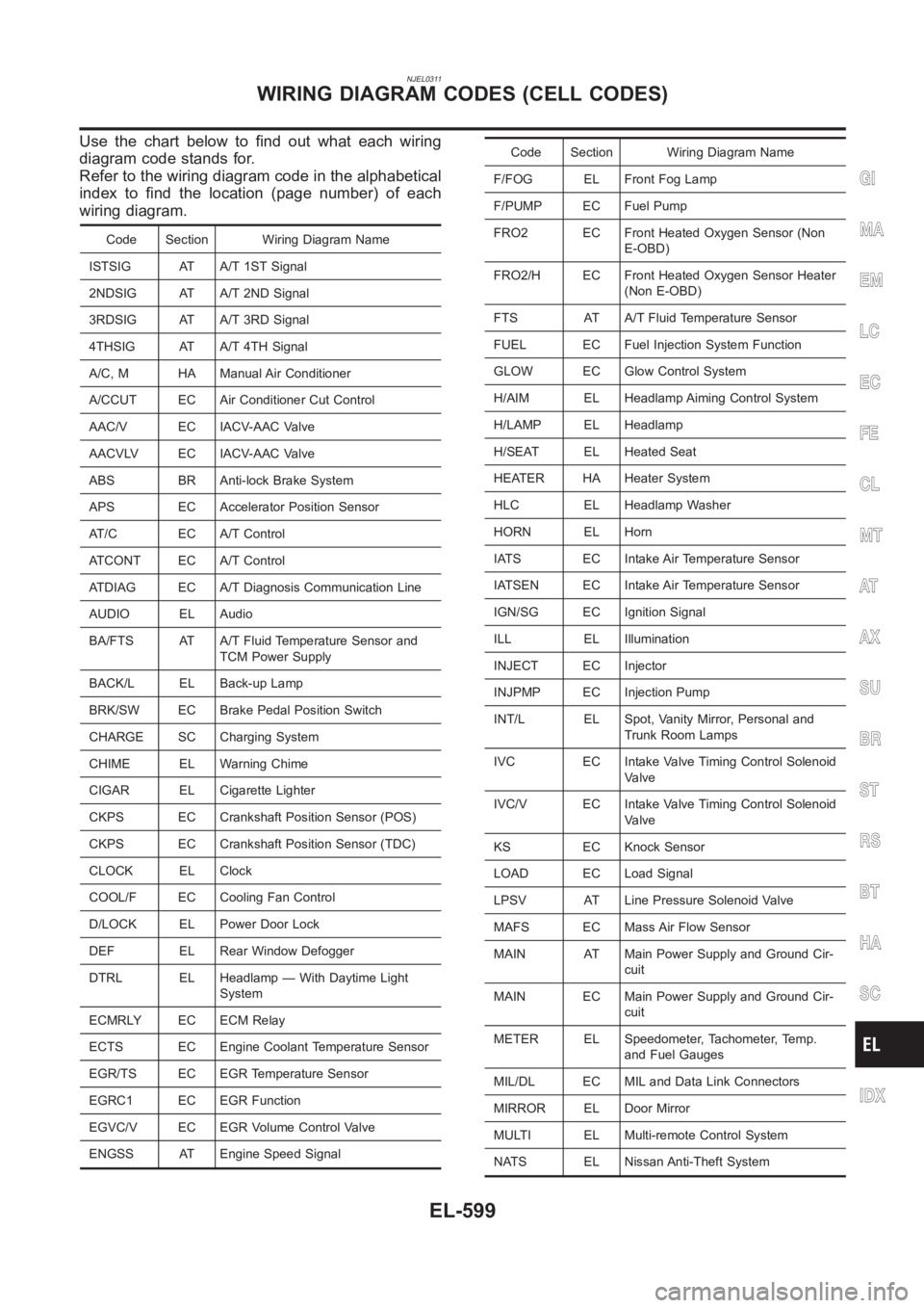
Use the chart below to find out what each wiring
diagram code stands for.
Refer to the wiring diagram code in the alphabetical
index to find the location (page number) of each
wiring diagram.
Code Section Wiring Diagram Name
ISTSIG AT A/T 1ST Signal
2NDSIG AT A/T 2ND Signal
3RDSIG AT A/T 3RD Signal
4THSIG AT A/T 4TH Signal
A/C, M HA Manual Air Conditioner
A/CCUT EC Air Conditioner Cut Control
AAC/V EC IACV-AAC Valve
AACVLV EC IACV-AAC Valve
ABS BR Anti-lock Brake System
APS EC Accelerator Position Sensor
AT/C EC A/T Control
ATCONT EC A/T Control
ATDIAG EC A/T Diagnosis Communication Line
AUDIO EL Audio
BA/FTS AT A/T Fluid Temperature Sensor and
TCM Power Supply
BACK/L EL Back-up Lamp
BRK/SW EC Brake Pedal Position Switch
CHARGE SC Charging System
CHIME EL Warning Chime
CIGAR EL Cigarette Lighter
CKPS EC Crankshaft Position Sensor (POS)
CKPS EC Crankshaft Position Sensor (TDC)
CLOCK EL Clock
COOL/F EC Cooling Fan Control
D/LOCK EL Power Door Lock
DEF EL Rear Window Defogger
DTRL EL Headlamp — With Daytime Light
System
ECMRLY EC ECM Relay
ECTS EC Engine Coolant Temperature Sensor
EGR/TS EC EGR Temperature Sensor
EGRC1 EC EGR Function
EGVC/V EC EGR Volume Control Valve
ENGSS AT Engine Speed Signal
Code Section Wiring Diagram Name
F/FOG EL Front Fog Lamp
F/PUMP EC Fuel Pump
FRO2 EC Front Heated Oxygen Sensor (Non
E-OBD)
FRO2/H EC Front Heated Oxygen Sensor Heater
(Non E-OBD)
FTS AT A/T Fluid Temperature Sensor
FUEL EC Fuel Injection System Function
GLOW EC Glow Control System
H/AIM EL Headlamp Aiming Control System
H/LAMP EL Headlamp
H/SEAT EL Heated Seat
HEATER HA Heater System
HLC EL Headlamp Washer
HORN EL Horn
IATS EC Intake Air Temperature Sensor
IATSEN EC Intake Air Temperature Sensor
IGN/SG EC Ignition Signal
ILL EL Illumination
INJECT EC Injector
INJPMP EC Injection Pump
INT/L EL Spot, Vanity Mirror, Personal and
Trunk Room Lamps
IVC EC Intake Valve Timing Control Solenoid
Valve
IVC/V EC Intake Valve Timing Control Solenoid
Valve
KS EC Knock Sensor
LOAD EC Load Signal
LPSV AT Line Pressure Solenoid Valve
MAFS EC Mass Air Flow Sensor
MAIN AT Main Power Supply and Ground Cir-
cuit
MAIN EC Main Power Supply and Ground Cir-
cuit
METER EL Speedometer, Tachometer, Temp.
and Fuel Gauges
MIL/DL EC MIL and Data Link Connectors
MIRROR EL Door Mirror
MULTI EL Multi-remote Control System
NATS EL Nissan Anti-Theft System
GI
MA
EM
LC
EC
FE
CL
MT
AT
AX
SU
BR
ST
RS
BT
HA
SC
IDX
WIRING DIAGRAM CODES (CELL CODES)
EL-599
Page 3007 of 3189
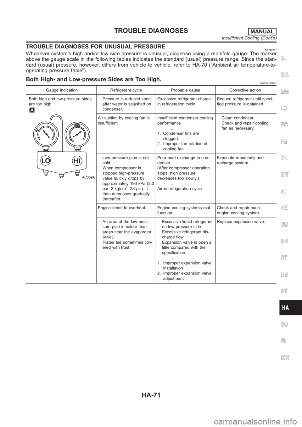
TROUBLE DIAGNOSES FOR UNUSUAL PRESSURENJHA0151Whenever system’s high and/or low side pressure is unusual, diagnose using a manifold gauge. The marker
above the gauge scale in the following tables indicates the standard (usual) pressure range. Since the stan-
dard (usual) pressure, however, differs from vehicle to vehicle, refer toHA-70 (“Ambient air temperature-to-
operating pressure table”).
Both High- and Low-pressure Sides are Too High.NJHA0151S01
Gauge indication Refrigerant cycle Probable cause Corrective action
Both high and low-pressure sides
are too high.
AC359A
Pressure is reduced soon
after water is splashed on
condenser.Excessive refrigerant charge
in refrigeration cycleReduce refrigerant until speci-
fied pressure is obtained.
Air suction by cooling fan is
insufficient.Insufficient condenser cooling
performance
"
1. Condenser fins are
clogged.
2. Improper fan rotation of
cooling fanClean condenser.
Check and repair cooling
fan as necessary.
Low-pressure pipe is not
cold.
When compressor is
stopped high-pressure
value quickly drops by
approximately 196 kPa (2.0
bar, 2 kg/cm
2, 28 psi). It
then decreases gradually
thereafter.Poor heat exchange in con-
denser
(After compressor operation
stops, high pressure
decreases too slowly.)
"
Air in refrigeration cycleEvacuate repeatedly and
recharge system.
Engine tends to overheat. Engine cooling systems mal-
function.Check and repair each
engine cooling system.
An area of the low-pres-
sure pipe is colder than
areas near the evaporator
outlet.
Plates are sometimes cov-
ered with frost.Excessive liquid refrigerant
on low-pressure side
Excessive refrigerant dis-
charge flow
Expansion valve is open a
little compared with the
specification.
"
1. Improper expansion valve
installation
2. Improper expansion valve
adjustmentReplace expansion valve.
GI
MA
EM
LC
EC
FE
CL
MT
AT
AX
SU
BR
ST
RS
BT
SC
EL
IDX
TROUBLE DIAGNOSESMANUAL
Insufficient Cooling (Cont’d)
HA-71
Page 3008 of 3189
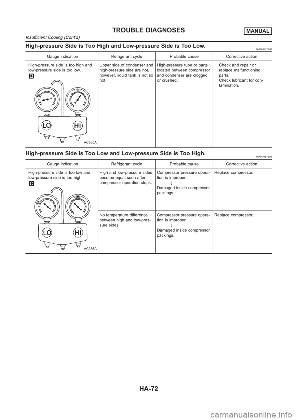
High-pressure Side is Too High and Low-pressure Side is Too Low.NJHA0151S02
Gauge indication Refrigerant cycle Probable cause Corrective action
High-pressure side is too high and
low-pressure side is too low.
AC360A
Upper side of condenser and
high-pressure side are hot,
however, liquid tank is not so
hot.High-pressure tube or parts
located between compressor
and condenser are clogged
or crushed.Check and repair or
replace malfunctioning
parts.
Check lubricant for con-
tamination.
High-pressure Side is Too Low and Low-pressure Side is Too High.NJHA0151S03
Gauge indication Refrigerant cycle Probable cause Corrective action
High-pressure side is too low and
low-pressure side is too high.
AC356A
High and low-pressure sides
become equal soon after
compressor operation stops.Compressor pressure opera-
tion is improper.
"
Damaged inside compressor
packingsReplace compressor.
No temperature difference
between high and low-pres-
sure sidesCompressor pressure opera-
tion is improper.
"
Damaged inside compressor
packings.Replace compressor.
TROUBLE DIAGNOSESMANUAL
Insufficient Cooling (Cont’d)
HA-72
Page 3009 of 3189
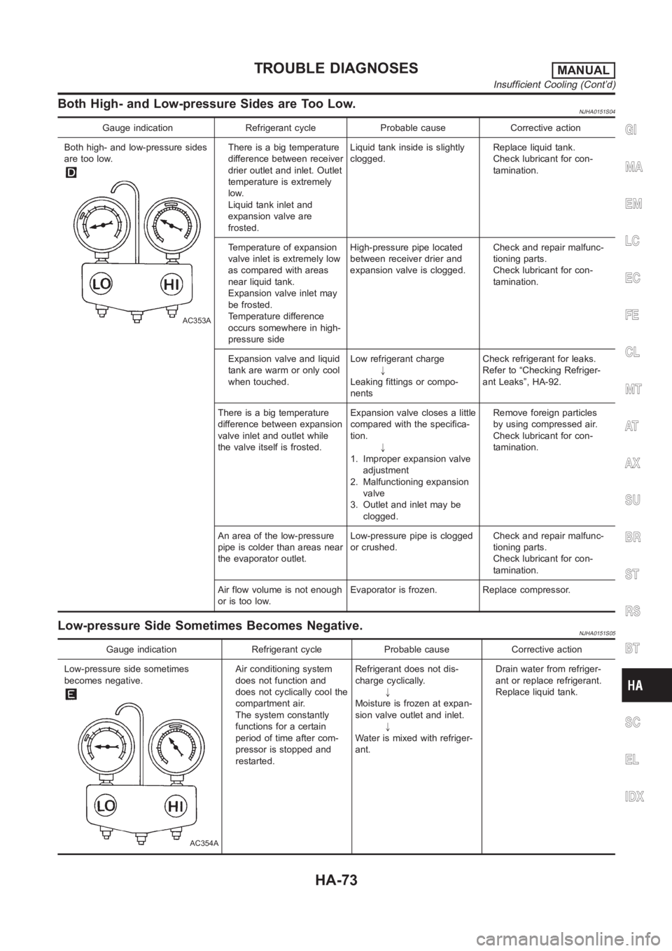
Both High- and Low-pressure Sides are Too Low.NJHA0151S04
Gauge indication Refrigerant cycle Probable cause Corrective action
Both high- and low-pressure sides
are too low.
AC353A
There is a big temperature
difference between receiver
drier outlet and inlet. Outlet
temperature is extremely
low.
Liquid tank inlet and
expansion valve are
frosted.Liquid tank inside is slightly
clogged.Replace liquid tank.
Check lubricant for con-
tamination.
Temperature of expansion
valve inlet is extremely low
as compared with areas
near liquid tank.
Expansion valve inlet may
be frosted.
Temperature difference
occurs somewhere in high-
pressure sideHigh-pressure pipe located
between receiver drier and
expansion valve is clogged.Check and repair malfunc-
tioning parts.
Check lubricant for con-
tamination.
Expansion valve and liquid
tank are warm or only cool
when touched.Low refrigerant charge
"
Leaking fittings or compo-
nentsCheck refrigerant for leaks.
Refer to “Checking Refriger-
ant Leaks”, HA-92.
There is a big temperature
difference between expansion
valve inlet and outlet while
the valve itself is frosted.Expansion valve closes a little
compared with the specifica-
tion.
"
1. Improper expansion valve
adjustment
2. Malfunctioning expansion
valve
3. Outlet and inlet may be
clogged.Remove foreign particles
by using compressed air.
Check lubricant for con-
tamination.
An area of the low-pressure
pipe is colder than areas near
the evaporator outlet.Low-pressure pipe is clogged
or crushed.Check and repair malfunc-
tioning parts.
Check lubricant for con-
tamination.
Air flow volume is not enough
or is too low.Evaporator is frozen. Replace compressor.
Low-pressure Side Sometimes Becomes Negative.NJHA0151S05
Gauge indication Refrigerant cycle Probable cause Corrective action
Low-pressure side sometimes
becomes negative.
AC354A
Air conditioning system
does not function and
does not cyclically cool the
compartment air.
The system constantly
functions for a certain
period of time after com-
pressor is stopped and
restarted.Refrigerant does not dis-
charge cyclically.
"
Moisture is frozen at expan-
sion valve outlet and inlet.
"
Water is mixed with refriger-
ant.Drain water from refriger-
ant or replace refrigerant.
Replace liquid tank.
GI
MA
EM
LC
EC
FE
CL
MT
AT
AX
SU
BR
ST
RS
BT
SC
EL
IDX
TROUBLE DIAGNOSESMANUAL
Insufficient Cooling (Cont’d)
HA-73
Page 3029 of 3189
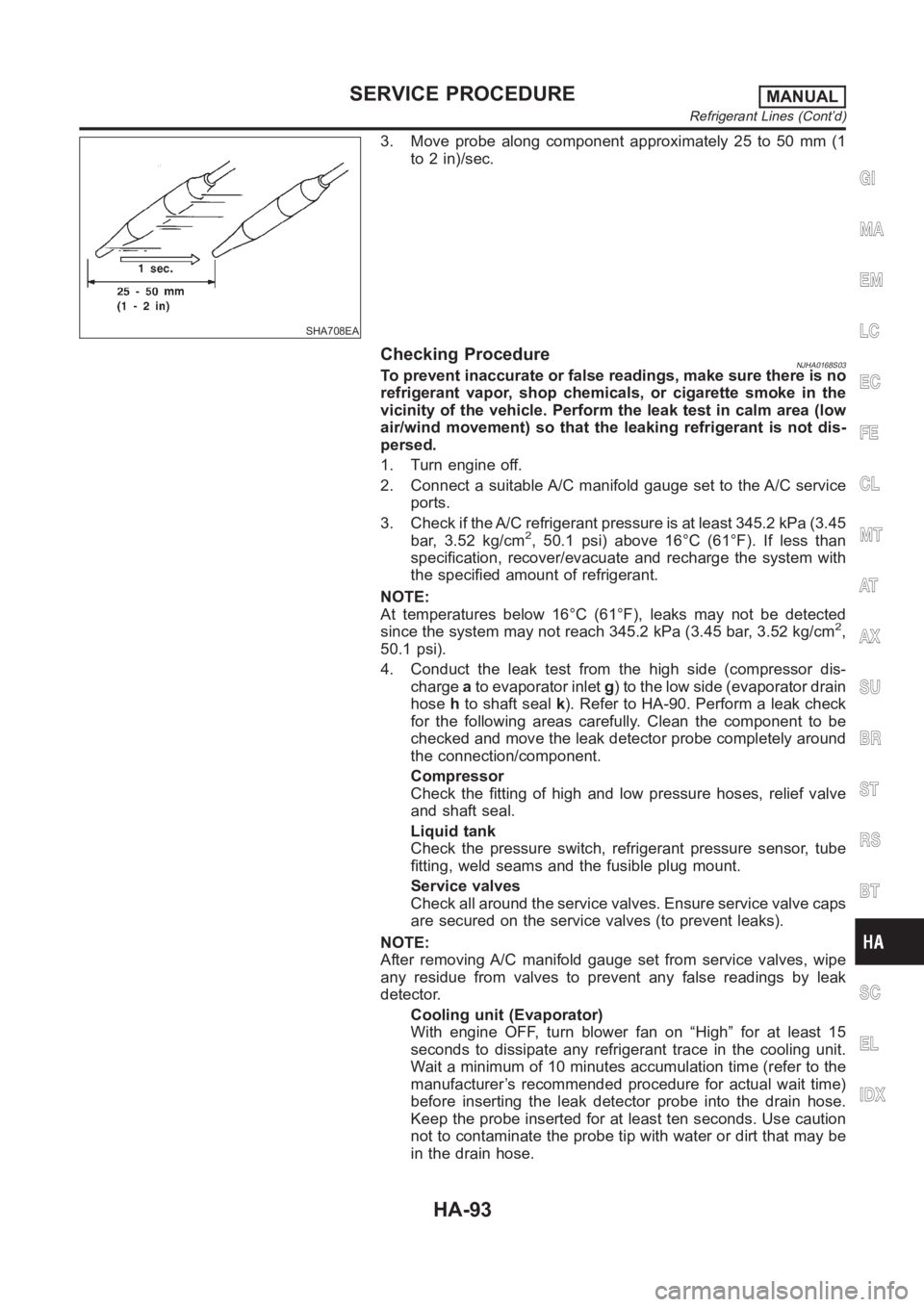
SHA708EA
3. Move probe along component approximately 25 to 50 mm (1
to 2 in)/sec.
Checking ProcedureNJHA0168S03To prevent inaccurate or false readings, make sure there is no
refrigerant vapor, shop chemicals, or cigarette smoke in the
vicinity of the vehicle. Perform the leak test in calm area (low
air/wind movement) so that the leaking refrigerant is not dis-
persed.
1. Turn engine off.
2. Connect a suitable A/C manifold gauge set to the A/C service
ports.
3. Check if the A/C refrigerant pressure is at least 345.2 kPa (3.45
bar, 3.52 kg/cm
2, 50.1 psi) above 16°C (61°F). If less than
specification, recover/evacuate and recharge the system with
the specified amount of refrigerant.
NOTE:
At temperatures below 16°C (61°F), leaks may not be detected
since the system may not reach 345.2 kPa (3.45 bar, 3.52 kg/cm
2,
50.1 psi).
4. Conduct the leak test from the high side (compressor dis-
chargeato evaporator inletg) to the low side (evaporator drain
hosehto shaft sealk). Refer to HA-90. Perform a leak check
for the following areas carefully. Clean the component to be
checked and move the leak detector probe completely around
the connection/component.
Compressor
Check the fitting of high and low pressure hoses, relief valve
and shaft seal.
Liquid tank
Check the pressure switch, refrigerant pressure sensor, tube
fitting, weld seams and the fusible plug mount.
Service valves
Check all around the service valves. Ensure service valve caps
are secured on the service valves (to prevent leaks).
NOTE:
After removing A/C manifold gauge set from service valves, wipe
any residue from valves to prevent any false readings by leak
detector.
Cooling unit (Evaporator)
With engine OFF, turn blower fan on “High” for at least 15
seconds to dissipate any refrigerant trace in the cooling unit.
Wait a minimum of 10 minutes accumulation time (refer to the
manufacturer’s recommended procedure for actual wait time)
before inserting the leak detector probe into the drain hose.
Keep the probe inserted for at least ten seconds. Use caution
not to contaminate the probe tip with water or dirt that may be
in the drain hose.
GI
MA
EM
LC
EC
FE
CL
MT
AT
AX
SU
BR
ST
RS
BT
SC
EL
IDX
SERVICE PROCEDUREMANUAL
Refrigerant Lines (Cont’d)
HA-93