2003 NISSAN ALMERA N16 Compression
[x] Cancel search: CompressionPage 425 of 3189
![NISSAN ALMERA N16 2003 Electronic Repair Manual TROUBLE DIAGNOSIS
EC-95
[QG (WITH EURO-OBD)]
C
D
E
F
G
H
I
J
K
L
MA
EC
ACTIVE TEST MODE
Test Item
*: Leaving cooling fan ″OFF″ with CONSULT-II while engine is running may cause the engine to overh NISSAN ALMERA N16 2003 Electronic Repair Manual TROUBLE DIAGNOSIS
EC-95
[QG (WITH EURO-OBD)]
C
D
E
F
G
H
I
J
K
L
MA
EC
ACTIVE TEST MODE
Test Item
*: Leaving cooling fan ″OFF″ with CONSULT-II while engine is running may cause the engine to overh](/manual-img/5/57350/w960_57350-424.png)
TROUBLE DIAGNOSIS
EC-95
[QG (WITH EURO-OBD)]
C
D
E
F
G
H
I
J
K
L
MA
EC
ACTIVE TEST MODE
Test Item
*: Leaving cooling fan ″OFF″ with CONSULT-II while engine is running may cause the engine to overheat.
DTC & SRT CONFIRMATION MODE
SRT STATUS Mode
For details, refer to EC-40, "SYSTEM READINESS TEST (SRT) CODE" .
SRT Work Support Mode
This mode enables a technician to drive a vehicle to set the SRT while monitoring the SRT status.
TEST ITEM CONDITION JUDGEMENT CHECK ITEM (REMEDY)
FUEL INJEC-
TION
●Engine: Return to the original
trouble condition
●Change the amount of fuel injec-
tion using CONSULT-II.If trouble symptom disappears, see
CHECK ITEM.
●Harness and connectors
●Fuel injectors
●Heated oxygen sensor 1
IGNITION TIM-
ING
●Engine: Return to the original
trouble condition
●Timing light: Set
●Retard the ignition timing using
CONSULT-II.If trouble symptom disappears, see
CHECK ITEM.
●Perform “Idle Air Volume Learn-
ing”.
POWER BAL-
ANCE
●Engine: After warming up, idle
the engine.
●A/C switch “OFF”
●Shift lever:
N (A/T models)
Neutral (M/T models)
●Cut off each injector signal one at
a time using CONSULT-II.Engine runs rough or dies.
●Harness and connectors
●Compression
●Fuel injectors
●Power transistor
●Spark plugs
●Ignition coils
COOLING FAN*
●Ignition switch: ON
●Turn the cooling fan “ON” and
“OFF” with CONSULT-II.Cooling fan moves and stops.
●Harness and connectors
●Cooling fan relay
●Cooling fan motor
ENG COOLANT
TEMP
●Engine: Return to the original
trouble condition
●Change the engine coolant tem-
perature using CONSULT-II.If trouble symptom disappears, see
CHECK ITEM.
●Harness and connectors
●Engine coolant temperature sen-
sor
●Fuel injectors
FUEL PUMP
RELAY
●Ignition switch: ON (Engine
stopped)
●Turn the fuel pump relay “ON”
and “OFF” using CONSULT-II
and listen to operating sound.Fuel pump relay makes the operat-
ing sound.●Harness and connectors
●Fuel pump relay
PURG VOL
CONT/V
●Engine: After warming up, run
engine at 1,500 rpm.
●Change the EVAP canister purge
volume control solenoid valve
opening percent using CON-
SULT-II.Engine speed changes according to
the opening percent.●Harness and connectors
●Solenoid valve
V/T ASSIGN
ANGLE
●Engine: Return to the original
trouble condition
●Change intake valve timing using
CONSULT-II.If trouble symptom disappears, see
CHECK ITEM.
●Harness and connectors
●Intake valve timing control sole-
noid valve
Page 555 of 3189
![NISSAN ALMERA N16 2003 Electronic Repair Manual DTC P0300 - P0304 MULTIPLE CYLINDER MISFIRE, NO. 1 - 4 CYLINDER MIS-
FIRE
EC-225
[QG (WITH EURO-OBD)]
C
D
E
F
G
H
I
J
K
L
MA
EC
DTC P0300 - P0304 MULTIPLE CYLINDER MISFIRE, NO. 1 - 4 CYLIND NISSAN ALMERA N16 2003 Electronic Repair Manual DTC P0300 - P0304 MULTIPLE CYLINDER MISFIRE, NO. 1 - 4 CYLINDER MIS-
FIRE
EC-225
[QG (WITH EURO-OBD)]
C
D
E
F
G
H
I
J
K
L
MA
EC
DTC P0300 - P0304 MULTIPLE CYLINDER MISFIRE, NO. 1 - 4 CYLIND](/manual-img/5/57350/w960_57350-554.png)
DTC P0300 - P0304 MULTIPLE CYLINDER MISFIRE, NO. 1 - 4 CYLINDER MIS-
FIRE
EC-225
[QG (WITH EURO-OBD)]
C
D
E
F
G
H
I
J
K
L
MA
EC
DTC P0300 - P0304 MULTIPLE CYLINDER MISFIRE, NO. 1 - 4 CYLINDER MIS-
FIRE
PFP:00000
On Board Diagnosis LogicEBS00K7U
When a misfire occurs, engine speed will fluctuate. If the engine speed fluctuates enough to cause the crank-
shaft position (CKP) sensor (POS) signal to vary, ECM can determine that a misfire is occurring.
The misfire detection logic consists of the following two conditions.
1. One Trip Detection Logic (Three Way Catalyst Damage)
On the first trip that a misfire condition occurs that can damage the three way catalyst (TWC) due to over-
heating, the MI will blink.
When a misfire condition occurs, the ECM monitors the CKP sensor (POS) signal every 200 engine revo-
lutions for a change.
When the misfire condition decreases to a level that will not damage the TWC, the MI will turn off.
If another misfire condition occurs that can damage the TWC on a second trip, the MI will blink.
When the misfire condition decreases to a level that will not damage the TWC, the MI will remain on.
If another misfire condition occurs that can damage the TWC, the MI will begin to blink again.
2. Two Trip Detection Logic (Exhaust quality deterioration)
For misfire conditions that will not damage the TWC (but will affect vehicle emissions), the MI will only light
when the misfire is detected on a second trip. During this condition, the ECM monitors the CKP sensor
signal every 1,000 engine revolutions.
A misfire malfunction can be detected on any one cylinder or on multiple cylinders.
DTC Confirmation ProcedureEBS00K7V
CAUTION:
Always drive vehicle at a safe speed.
NOTE:
If “DTC Confirmation Procedure” has been previously conducted, always turn ignition switch “OFF” and wait at
least 10 seconds before conducting the next test.
Sensor Input Signal to ECM ECM function
Crankshaft position sensor (POS) Engine speed On board diagnosis of misfire
DTC No. Trouble diagnosis name DTC detecting condition Possible cause
P0300
0300Multiple cylinder misfire
detectedMultiple cylinder misfire.
●Improper spark plug
●Insufficient compression
●Incorrect fuel pressure
●The injector circuit is open or shorted
●Fuel injectors
●Intake air leak
●The ignition signal circuit is open or
shorted
●Lack of fuel
●Drive plate or flywheel
●Heated oxygen sensor 1
●Incorrect PCV hose connection P0301
0301No.1 cylinder misfire
detectedNo. 1 cylinder misfires.
P0302
0302No. 2 cylinder misfire
detectedNo. 2 cylinder misfires.
P0303
0303No. 3 cylinder misfire
detectedNo. 3 cylinder misfires.
P0304
0304No. 4 cylinder misfire
detectedNo. 4 cylinder misfires.
Page 558 of 3189
![NISSAN ALMERA N16 2003 Electronic Repair Manual EC-228
[QG (WITH EURO-OBD)]
DTC P0300 - P0304 MULTIPLE CYLINDER MISFIRE, NO. 1 - 4 CYLINDER MIS-
FIRE
6. CHECK SPARK PLUGS
Remove the spark plugs and check for fouling, etc.
OK or NG
OK >> GO TO 7.
NG NISSAN ALMERA N16 2003 Electronic Repair Manual EC-228
[QG (WITH EURO-OBD)]
DTC P0300 - P0304 MULTIPLE CYLINDER MISFIRE, NO. 1 - 4 CYLINDER MIS-
FIRE
6. CHECK SPARK PLUGS
Remove the spark plugs and check for fouling, etc.
OK or NG
OK >> GO TO 7.
NG](/manual-img/5/57350/w960_57350-557.png)
EC-228
[QG (WITH EURO-OBD)]
DTC P0300 - P0304 MULTIPLE CYLINDER MISFIRE, NO. 1 - 4 CYLINDER MIS-
FIRE
6. CHECK SPARK PLUGS
Remove the spark plugs and check for fouling, etc.
OK or NG
OK >> GO TO 7.
NG >> Repair or replace spark plug(s) with standard type
one(s). For spark plug type, refer to MA-7.
7. CHECK COMPRESSION PRESSURE
Check compression pressure. Refer to EM-57, "
CHECKING COMPRESSION PRESSURE" .
QG15DE engine
QG18DE engine
OK or NG
OK >> GO TO 8.
NG >> Check pistons, piston rings, valves, valve seats and cylinder head gaskets.
8. CHECK FUEL PRESSURE
1. Install all removed parts.
2. Release fuel pressure to zero. Refer to EC-34, "
FUEL PRESSURE RELEASE" .
3. Install fuel pressure gauge and check fuel pressure. Refer to EC-34, "
FUEL PRESSURE CHECK" .
OK or NG
OK >> GO TO 9.
NG >> Follow the construction of “FUEL PRESSURE CHECK”.
SEF156I
Standard:
1,372 kPa (13.720 bar, 13.99 kg/cm2 , 198.9 psi)/350 rpm
Minimum:
1,176 kPa (11.759 bar, 11.99 kg/cm
2 , 170.5 psi)/350 rpm
Difference between each
cylinder:98 kPa (0.98 bar, 1.0 kg/cm
2 , 14 psi)/350 rpm
Standard:
1,324 kPa (13.24 bar, 13.5 kg/cm
2 , 192 psi)/350 rpm
Minimum:
1,128 kPa (11.28 bar, 11.5 kg/cm
2 , 164 psi)/350 rpm
Difference between each
cylinder:98 kPa (0.98 bar, 1.0 kg/cm
2 , 14 psi)/350 rpm
At idle: Approx. 350 kPa (3.5 bar, 3.57 kg/cm
2 , 51 psi)
Page 803 of 3189
![NISSAN ALMERA N16 2003 Electronic Repair Manual TROUBLE DIAGNOSIS
EC-473
[QG (WITHOUT EURO-OBD)]
C
D
E
F
G
H
I
J
K
L
MA
EC
ACTIVE TEST MODE
Test Item
*: Leaving cooling fan ″OFF″ with CONSULT-II while engine is running may cause the engine to o NISSAN ALMERA N16 2003 Electronic Repair Manual TROUBLE DIAGNOSIS
EC-473
[QG (WITHOUT EURO-OBD)]
C
D
E
F
G
H
I
J
K
L
MA
EC
ACTIVE TEST MODE
Test Item
*: Leaving cooling fan ″OFF″ with CONSULT-II while engine is running may cause the engine to o](/manual-img/5/57350/w960_57350-802.png)
TROUBLE DIAGNOSIS
EC-473
[QG (WITHOUT EURO-OBD)]
C
D
E
F
G
H
I
J
K
L
MA
EC
ACTIVE TEST MODE
Test Item
*: Leaving cooling fan ″OFF″ with CONSULT-II while engine is running may cause the engine to overheat.
REAL TIME DIAGNOSIS IN DATA MONITOR MODE (RECORDING VEHICLE DATA)
Description
CONSULT-II has two kinds of triggers and they can be selected by touching “SETTING” in “DATA MONITOR”
mode.
1. “AUTO TRIG” (Automatic trigger):
TEST ITEM CONDITION JUDGEMENT CHECK ITEM (REMEDY)
FUEL INJEC-
TION
●Engine: Return to the original
trouble condition
●Change the amount of fuel injec-
tion using CONSULT-II.If trouble symptom disappears, see
CHECK ITEM.
●Harness and connectors
●Fuel injectors
●Heated oxygen sensor 1
IGNITION TIM-
ING
●Engine: Return to the original
trouble condition
●Timing light: Set
●Retard the ignition timing using
CONSULT-II.If trouble symptom disappears, see
CHECK ITEM.
●Perform “Idle Air Volume Learn-
ing”.
POWER BAL-
ANCE
●Engine: After warming up, idle
the engine.
●A/C switch “OFF”
●Shift lever:
N (A/T models)
Neutral (M/T models)
●Cut off each injector signal one at
a time using CONSULT-II.Engine runs rough or dies.
●Harness and connectors
●Compression
●Fuel injectors
●Power transistor
●Spark plugs
●Ignition coils
COOLING FAN*
●Ignition switch: ON
●Turn the cooling fan “ON” and
“OFF” with CONSULT-II.Cooling fan moves and stops.
●Harness and connectors
●Cooling fan relay
●Cooling fan motor
ENG COOLANT
TEMP
●Engine: Return to the original
trouble condition
●Change the engine coolant tem-
perature using CONSULT-II.If trouble symptom disappears, see
CHECK ITEM.
●Harness and connectors
●Engine coolant temperature sen-
sor
●Fuel injectors
FUEL PUMP
RELAY
●Ignition switch: ON (Engine
stopped)
●Turn the fuel pump relay “ON”
and “OFF” using CONSULT-II
and listen to operating sound.Fuel pump relay makes the operat-
ing sound.●Harness and connectors
●Fuel pump relay
PURG VOL
CONT/V
●Engine: After warming up, run
engine at 1,500 rpm.
●Change the EVAP canister purge
volume control solenoid valve
opening percent using CON-
SULT-II.Engine speed changes according to
the opening percent.●Harness and connectors
●Solenoid valve
V/T ASSIGN
ANGLE
●Engine: Return to the original
trouble condition
●Change intake valve timing using
CONSULT-II.If trouble symptom disappears, see
CHECK ITEM.
●Harness and connectors
●Intake valve timing control sole-
noid valve
Page 1105 of 3189

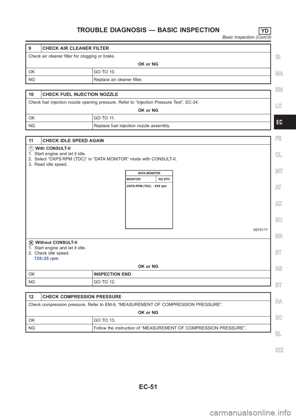
9 CHECK AIR CLEANER FILTER
Check air cleaner filter for clogging or braks.
OK or NG
OK GO TO 10.
NG Replace air cleaner filter.
10 CHECK FUEL INJECTION NOZZLE
Check fuel injection nozzle opening pressure. Refer to “Injection Pressure Test”, EC-24.
OK or NG
OK GO TO 11.
NG Replace fuel injection nozzle assembly.
11 CHECK IDLE SPEED AGAIN
With CONSULT-II
1. Start engine and let it idle.
2. Select “CKPS·RPM (TDC)” in “DATA MONITOR” mode with CONSULT-II.
3. Read idle speed.
SEF817Y
Without CONSULT-II
1. Start engine and let it idle.
2. Check idle speed.
725±25 rpm
OK or NG
OKINSPECTION END
NG GO TO 12.
12 CHECK COMPRESSION PRESSURE
Check compression pressure. Refer to EM-9, “MEASUREMENT OF COMPRESSION PRESSURE”.
OK or NG
OK GO TO 13.
NG Follow the instruction of “MEASUREMENT OF COMPRESSION PRESSURE”.
GI
MA
EM
LC
FE
CL
MT
AT
AX
SU
BR
ST
RS
BT
HA
SC
EL
IDX
TROUBLE DIAGNOSIS — BASIC INSPECTIONYD
Basic Inspection (Cont’d)
EC-51
Page 1107 of 3189

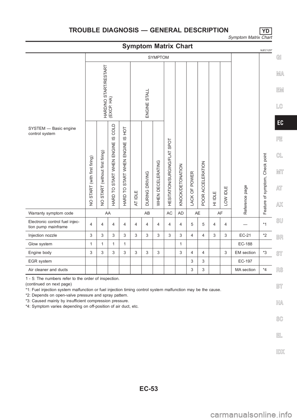
Symptom Matrix ChartNJEC1257
SYSTEM — Basic engine
control systemSYMPTOM
Reference page
Feature of symptom, Check pointHARD/NO START/RESTART
(EXCP. HA)
ENGINE STALL
HESITATION/SURGING/FLAT SPOT
KNOCK/DETONATION
LACK OF POWER
POOR ACCELERATION
HI IDLE
LOW IDLE NO START (with first firing)
NO START (without first firing)
HARD TO START WHEN ENGINE IS COLD
HARD TO START WHEN ENGINE IS HOT
AT IDLE
DURING DRIVING
WHEN DECELERATINGWarranty symptom code AA AB AC AD AE AF
Electronic control fuel injec-
tion pump mainframe4444444445544 — *1
Injection nozzle 3 3 3 3333334433 EC-21 *2
Glow system 1 1 1 1 1 EC-188
Engine body 3 3 3 3 3 3 3 3 4 4 3 EM section *3
EGR system3 3 EC-197
Air cleaner and ducts 3 3 MA section *4
1 - 5: The numbers refer to the order of inspection.
(continued on next page)
*1: Fuel injection system malfunction or fuel injection timing control system malfunction may be the cause.
*2: Depends on open-valve pressure and spray pattern.
*3: Caused mainly by insufficient compression pressure.
*4: Symptom varies depending on off-position of air duct, etc.
GI
MA
EM
LC
FE
CL
MT
AT
AX
SU
BR
ST
RS
BT
HA
SC
EL
IDX
TROUBLE DIAGNOSIS — GENERAL DESCRIPTIONYD
Symptom Matrix Chart
EC-53
Page 1108 of 3189

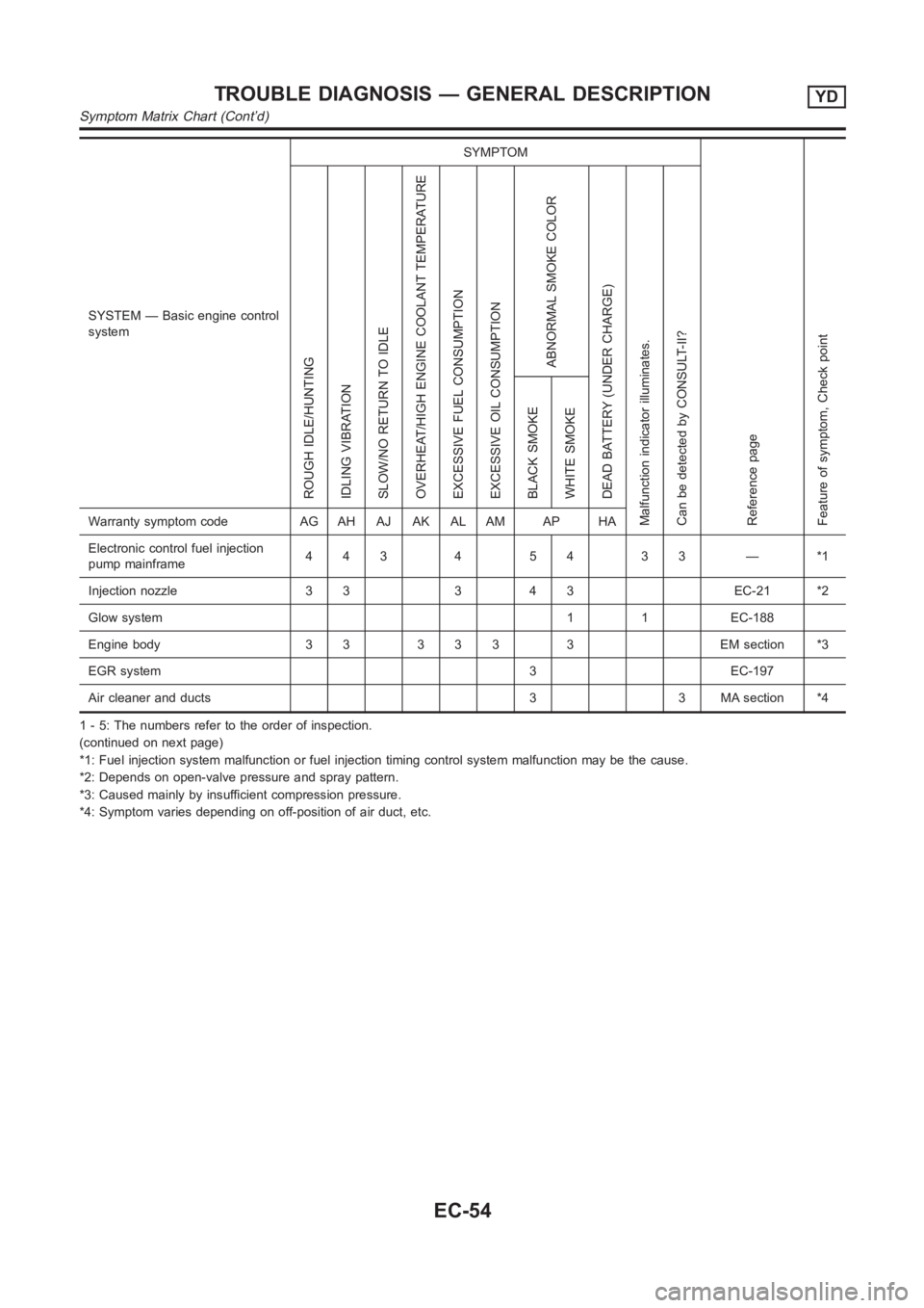
SYSTEM — Basic engine control
systemSYMPTOM
Reference page
Feature of symptom, Check pointROUGH IDLE/HUNTING
IDLING VIBRATION
SLOW/NO RETURN TO IDLE
OVERHEAT/HIGH ENGINE COOLANT TEMPERATURE
EXCESSIVE FUEL CONSUMPTION
EXCESSIVE OIL CONSUMPTION
ABNORMAL SMOKE COLOR
DEAD BATTERY (UNDER CHARGE)
Malfunction indicator illuminates.
Can be detected by CONSULT-II?BLACK SMOKE
WHITE SMOKEWarranty symptom code AG AH AJ AK AL AM AP HA
Electronic control fuel injection
pump mainframe44345433—*1
Injection nozzle 3 3 3 4 3 EC-21 *2
Glow system 1 1 EC-188
Engine body 3 3 3 3 3 3 EM section *3
EGR system 3 EC-197
Air cleaner and ducts 3 3 MA section *4
1 - 5: The numbers refer to the order of inspection.
(continued on next page)
*1: Fuel injection system malfunction or fuel injection timing control system malfunction may be the cause.
*2: Depends on open-valve pressure and spray pattern.
*3: Caused mainly by insufficient compression pressure.
*4: Symptom varies depending on off-position of air duct, etc.
TROUBLE DIAGNOSIS — GENERAL DESCRIPTIONYD
Symptom Matrix Chart (Cont’d)
EC-54
Page 3177 of 3189

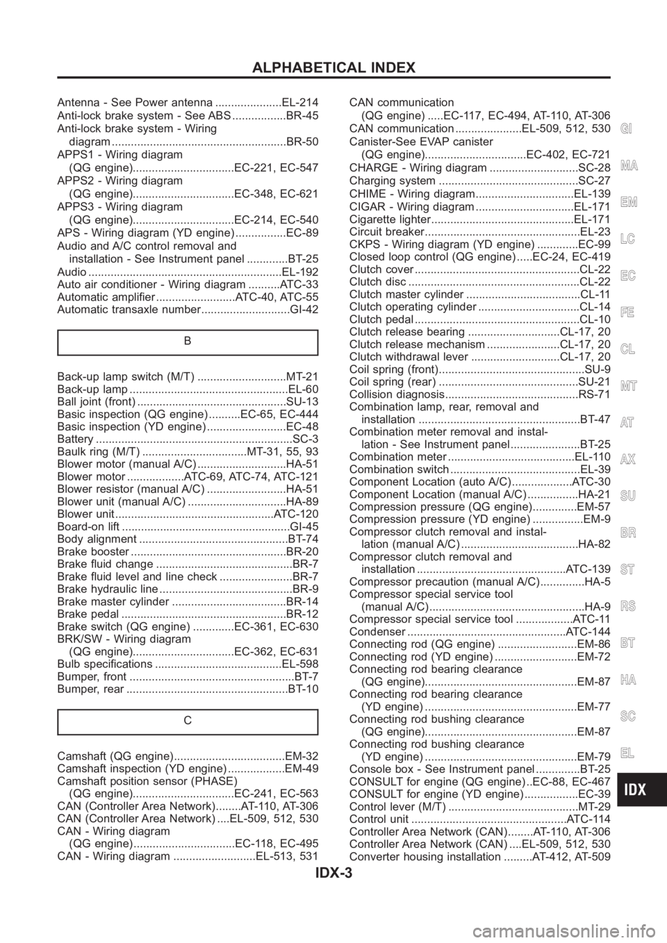
Antenna - See Power antenna .....................EL-214
Anti-lock brake system - See ABS .................BR-45
Anti-lock brake system - Wiring
diagram <0011001100110011001100110011001100110011001100110011001100110011001100110011001100110011001100110011001100110011001100110011001100110011001100110011001100110011001100110011001100110011001100110011001100
1100110011001100110025[R-50
APPS1 - Wiring diagram
(QG engine)................................EC-221, EC-547
APPS2 - Wiring diagram
(QG engine)................................EC-348, EC-621
APPS3 - Wiring diagram
(QG engine)................................EC-214, EC-540
APS - Wiring diagram (YD engine) ................EC-89
Audio and A/C control removal and
installation - See Instrument panel .............BT-25
Audio <0011001100110011001100110011001100110011001100110011001100110011001100110011001100110011001100110011001100110011001100110011001100110011001100110011001100110011001100110011001100110011001100110011001100
110011001100110011001100110011[...EL-192
Auto air conditioner - Wiring diagram ..........ATC-33
Automatic amplifier .........................ATC-40, ATC-55
Automatic transaxle number............................GI-42
B
Back-up lamp switch (M/T) ............................MT-21
Back-up lamp <0011001100110011001100110011001100110011001100110011001100110011001100110011001100110011001100110011001100110011001100110011001100110011001100110011001100110011001100110011001100110011001100110011001100
28002f[-60
Ball joint (front) ...............................................SU-13
Basic inspection (QG engine) ..........EC-65, EC-444
Basic inspection (YD engine) .........................EC-48
Battery <0011001100110011001100110011001100110011001100110011001100110011001100110011001100110011001100110011001100110011001100110011001100110011001100110011001100110011001100110011001100110011001100110011001100
1100110011001100110011[......SC-3
Baulk ring (M/T) .................................MT-31, 55, 93
Blower motor (manual A/C) ............................HA-51
Blower motor ..................ATC-69, ATC-74, ATC-121
Blower resistor (manual A/C) .........................HA-51
Blower unit (manual A/C) ...............................HA-89
Blower unit <0011001100110011001100110011001100110011001100110011001100110011001100110011001100110011001100110011001100110011001100110011001100110011001100110011001100110011001100110011001100110011001100110011001100
24>�7�C-120
Board-on lift <0011001100110011001100110011001100110011001100110011001100110011001100110011001100110011001100110011001100110011001100110011001100110011001100110011001100110011001100110011001100110011001100110011001100
11[..GI-45
Body alignment ...............................................BT-74
Brake booster .................................................BR-20
Brake fluid change ...........................................BR-7
Brake fluid level and line check .......................BR-7
Brake hydraulic line ..........................................BR-9
Brake master cylinder ....................................BR-14
Brake pedal <0011001100110011001100110011001100110011001100110011001100110011001100110011001100110011001100110011001100110011001100110011001100110011001100110011001100110011001100110011001100110011001100110011001100
1100110025[R-12
Brake switch (QG engine) .............EC-361, EC-630
BRK/SW - Wiring diagram
(QG engine)................................EC-362, EC-631
Bulb specifications ........................................EL-598
Bumper, front <0011001100110011001100110011001100110011001100110011001100110011001100110011001100110011001100110011001100110011001100110011001100110011001100110011001100110011001100110011001100110011001100110011001100
11[.BT-7
Bumper, rear <0011001100110011001100110011001100110011001100110011001100110011001100110011001100110011001100110011001100110011001100110011001100110011001100110011001100110011001100110011001100110011001100110011001100
110025[T- 1 0
C
Camshaft (QG engine)...................................EM-32
Camshaft inspection (YD engine) ..................EM-49
Camshaft position sensor (PHASE)
(QG engine)................................EC-241, EC-563
CAN (Controller Area Network)........AT-110, AT-306
CAN (Controller Area Network) ....EL-509, 512, 530
CAN - Wiring diagram
(QG engine) ................................EC-118, EC-495
CAN - Wiring diagram ..........................EL-513, 531CAN communication
(QG engine) .....EC-117, EC-494, AT-110, AT-306
CAN communication .....................EL-509, 512, 530
Canister-See EVAP canister
(QG engine)................................EC-402, EC-721
CHARGE - Wiring diagram ............................SC-28
Charging system ............................................SC-27
CHIME - Wiring diagram...............................EL-139
CIGAR - Wiring diagram ...............................EL-171
Cigarette lighter.............................................EL-171
Circuit breaker.................................................EL-23
CKPS - Wiring diagram (YD engine) .............EC-99
Closed loop control (QG engine) .....EC-24, EC-419
Clutch cover <0011001100110011001100110011001100110011001100110011001100110011001100110011001100110011001100110011001100110011001100110011001100110011001100110011001100110011001100110011001100110011001100110011001100
110011[CL-22
Clutch disc <0011001100110011001100110011001100110011001100110011001100110011001100110011001100110011001100110011001100110011001100110011001100110011001100110011001100110011001100110011001100110011001100110011001100
1100110011[.CL-22
Clutch master cylinder ....................................CL-11
Clutch operating cylinder ................................CL-14
Clutch pedal <0011001100110011001100110011001100110011001100110011001100110011001100110011001100110011001100110011001100110011001100110011001100110011001100110011001100110011001100110011001100110011001100110011001100
110011[CL-10
Clutch release bearing .............................CL-17, 20
Clutch release mechanism .......................CL-17, 20
Clutch withdrawal lever ............................CL-17, 20
Coil spring (front)..............................................SU-9
Coil spring (rear) ............................................SU-21
Collision diagnosis..........................................RS-71
Combination lamp, rear, removal and
installation <0011001100110011001100110011001100110011001100110011001100110011001100110011001100110011001100110011001100110011001100110011001100110011001100110011001100110011001100110011001100110011001100110011001100
11[BT-47
Combination meter removal and instal-
lation - See Instrument panel ......................BT-25
Combination meter ........................................EL-110
Combination switch .........................................EL-39
Component Location (auto A/C) ...................ATC-30
Component Location (manual A/C) ................HA-21
Compression pressure (QG engine)..............EM-57
Compression pressure (YD engine) ................EM-9
Compressor clutch removal and instal-
lation (manual A/C) .....................................HA-82
Compressor clutch removal and
installation ...............................................ATC-139
Compressor precaution (manual A/C)..............HA-5
Compressor special service tool
(manual A/C) .................................................HA-9
Compressor special service tool ..................ATC-11
Condenser <0011001100110011001100110011001100110011001100110011001100110011001100110011001100110011001100110011001100110011001100110011001100110011001100110011001100110011001100110011001100110011001100110011001100
24>�7�&�-144
Connecting rod (QG engine) .........................EM-86
Connecting rod (YD engine) ..........................EM-72
Connecting rod bearing clearance
(QG engine)................................................EM-87
Connecting rod bearing clearance
(YD engine) ................................................EM-77
Connecting rod bushing clearance
(QG engine)................................................EM-87
Connecting rod bushing clearance
(YD engine) ................................................EM-79
Console box - See Instrument panel ..............BT-25
CONSULT for engine (QG engine) ..EC-88, EC-467
CONSULT for engine (YD engine) .................EC-39
Control lever (M/T) .........................................MT-29
Control unit .................................................ATC-114
Controller Area Network (CAN)........AT-110, AT-306
Controller Area Network (CAN) ....EL-509, 512, 530
Converter housing installation .........AT-412, AT-509
GI
MA
EM
LC
EC
FE
CL
MT
AT
AX
SU
BR
ST
RS
BT
HA
SC
EL
ALPHABETICAL INDEX
IDX-3