Page 230 of 3189
CAUTION:
When installing camshafts, chain tensioners, oil seals, or
other sliding parts, lubricate contacting surfaces with new
engine oil.
Apply new engine oil to threads and seat surfaces when
installing cylinder head, camshaft sprocket, crankshaft
pulley, and camshaft bracket.
Attach tags to valve lifters so as not to mix them up.
RemovalNJEM0063PREPARATIVE WORKNJEM0063S011. Drain engine coolant. Refer to LC-43, “Changing Engine Cool-
ant”.
2. Remove exhaust manifold. Refer to EM-38, “Removal”.
3. Remove intake manifold. Refer to EM-34, “Removal”.
Apply paint to camshaft sprockets for alignment during
installation.
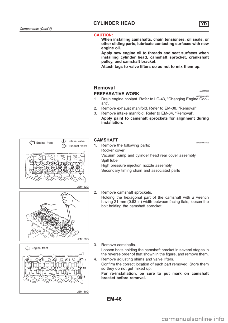
JEM152G
CAMSHAFTNJEM0063S021. Remove the following parts:
Rocker cover
Vacuum pump and cylinder head rear cover assembly
Spill tube
High pressure injection nozzle assembly
Secondary timing chain and associated parts
JEM159G
2. Remove camshaft sprockets.
Holding the hexagonal part of the camshaft with a wrench
having 21 mm (0.83 in) width between facing flats, loosen the
bolt holding the camshaft sprocket.
JEM160G
3. Remove camshafts.
Loosen bolts holding the camshaft bracket in several stages in
the reverse order of that shown in the figure, and remove them.
4. Remove adjusting shims and valve lifters.
Confirm the correct location of each part removed. Store them
so they do not get mixed up.
For re-installation, be sure to put mark on camshaft
bracket before removal.
CYLINDER HEADYD
Components (Cont’d)
EM-46
Page 252 of 3189
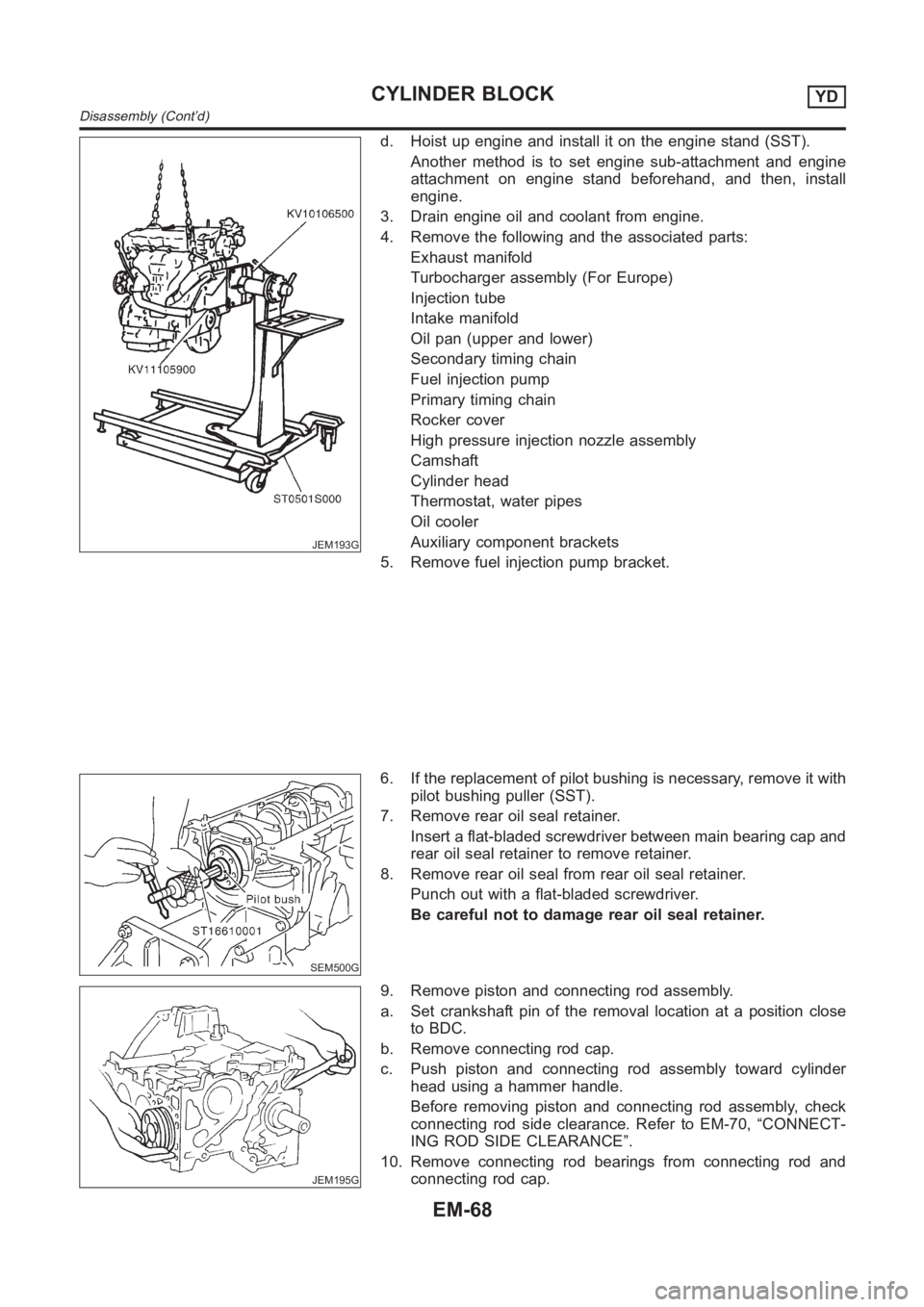
JEM193G
d. Hoist up engine and install it on the engine stand (SST).
Another method is to set engine sub-attachment and engine
attachment on engine stand beforehand, and then, install
engine.
3. Drain engine oil and coolant from engine.
4. Remove the following and the associated parts:
Exhaust manifold
Turbocharger assembly (For Europe)
Injection tube
Intake manifold
Oil pan (upper and lower)
Secondary timing chain
Fuel injection pump
Primary timing chain
Rocker cover
High pressure injection nozzle assembly
Camshaft
Cylinder head
Thermostat, water pipes
Oil cooler
Auxiliary component brackets
5. Remove fuel injection pump bracket.
SEM500G
6. If the replacement of pilot bushing is necessary, remove it with
pilot bushing puller (SST).
7. Remove rear oil seal retainer.
Insert a flat-bladed screwdriver between main bearing cap and
rear oil seal retainer to remove retainer.
8. Remove rear oil seal from rear oil seal retainer.
Punch out with a flat-bladed screwdriver.
Be careful not to damage rear oil seal retainer.
JEM195G
9. Remove piston and connecting rod assembly.
a. Set crankshaft pin of the removal location at a position close
to BDC.
b. Remove connecting rod cap.
c. Push piston and connecting rod assembly toward cylinder
head using a hammer handle.
Before removing piston and connecting rod assembly, check
connecting rod side clearance. Refer to EM-70, “CONNECT-
ING ROD SIDE CLEARANCE”.
10. Remove connecting rod bearings from connecting rod and
connecting rod cap.
CYLINDER BLOCKYD
Disassembly (Cont’d)
EM-68
Page 270 of 3189
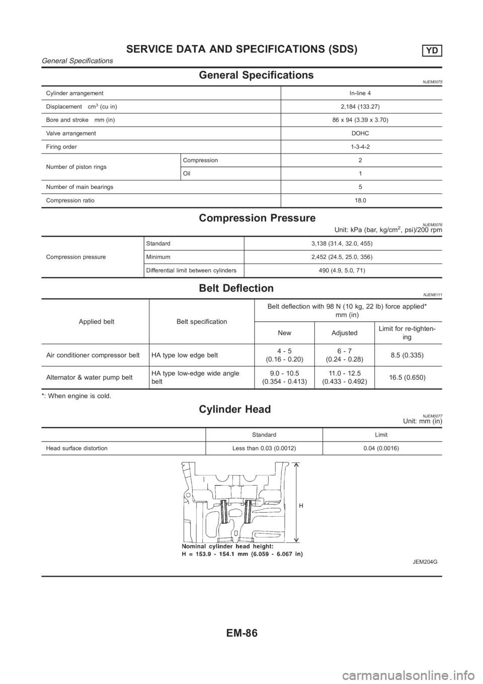
General SpecificationsNJEM0075
Cylinder arrangementIn-line 4
Displacement cm
3(cu in)2,184 (133.27)
Bore and stroke mm (in)86 x 94 (3.39 x 3.70)
Valve arrangementDOHC
Firing order1-3-4-2
Number of piston ringsCompression 2
Oil 1
Number of main bearings5
Compression ratio18.0
Compression PressureNJEM0076Unit: kPa (bar, kg/cm2, psi)/200 rpm
Compression pressureStandard 3,138 (31.4, 32.0, 455)
Minimum 2,452 (24.5, 25.0, 356)
Differential limit between cylinders 490 (4.9, 5.0, 71)
Belt DeflectionNJEM0111
Applied belt Belt specificationBelt deflection with 98 N (10 kg, 22 lb) force applied*
mm (in)
New AdjustedLimit for re-tighten-
ing
Air conditioner compressor belt HA type low edge belt4-5
(0.16 - 0.20)6-7
(0.24 - 0.28)8.5 (0.335)
Alternator & water pump beltHA type low-edge wide angle
belt9.0 - 10.5
(0.354 - 0.413)11 . 0 - 1 2 . 5
(0.433 - 0.492)16.5 (0.650)
*: When engine is cold.
Cylinder HeadNJEM0077Unit: mm (in)
Standard Limit
Head surface distortion Less than 0.03 (0.0012) 0.04 (0.0016)
JEM204G
SERVICE DATA AND SPECIFICATIONS (SDS)YD
General Specifications
EM-86
Page 289 of 3189
SEM855F
SEM856F
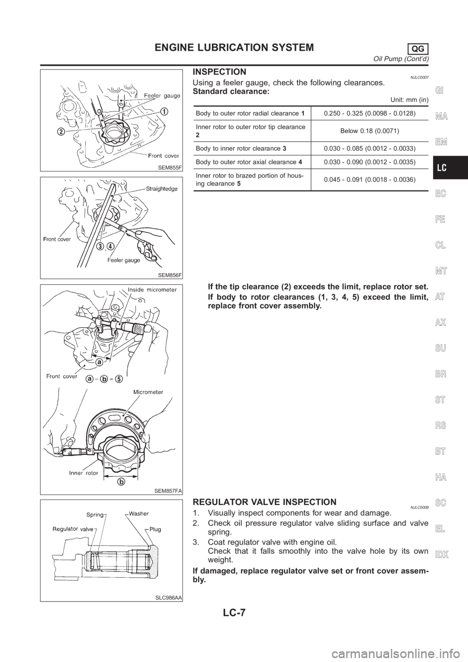
INSPECTIONNJLC0007Using a feeler gauge, check the following clearances.
Standard clearance:
Unit: mm (in)
Body to outer rotor radial clearance10.250 - 0.325 (0.0098 - 0.0128)
Inner rotor to outer rotor tip clearance
2Below 0.18 (0.0071)
Body to inner rotor clearance30.030 - 0.085 (0.0012 - 0.0033)
Body to outer rotor axial clearance40.030 - 0.090 (0.0012 - 0.0035)
Inner rotor to brazed portion of hous-
ing clearance50.045 - 0.091 (0.0018 - 0.0036)
SEM857FA
If the tip clearance (2) exceeds the limit, replace rotor set.
If body to rotor clearances (1, 3, 4, 5) exceed the limit,
replace front cover assembly.
SLC986AA
REGULATOR VALVE INSPECTIONNJLC00081. Visually inspect components for wear and damage.
2. Check oil pressure regulator valve sliding surface and valve
spring.
3. Coat regulator valve with engine oil.
Check that it falls smoothly into the valve hole by its own
weight.
If damaged, replace regulator valve set or front cover assem-
bly.
GI
MA
EM
EC
FE
CL
MT
AT
AX
SU
BR
ST
RS
BT
HA
SC
EL
IDX
ENGINE LUBRICATION SYSTEMQG
Oil Pump (Cont’d)
LC-7
Page 292 of 3189
Service Data and Specifications (SDS)
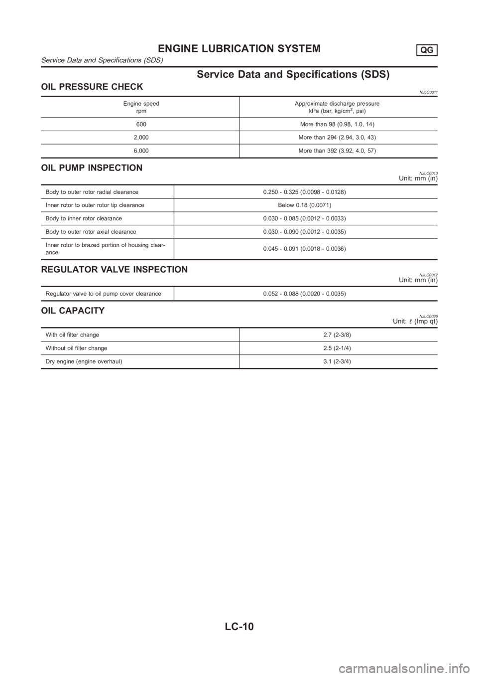
OIL PRESSURE CHECKNJLC0011
Engine speed
rpmApproximate discharge pressure
kPa (bar, kg/cm2, psi)
600 More than 98 (0.98, 1.0, 14)
2,000 More than 294 (2.94, 3.0, 43)
6,000 More than 392 (3.92, 4.0, 57)
OIL PUMP INSPECTIONNJLC0013Unit: mm (in)
Body to outer rotor radial clearance 0.250 - 0.325 (0.0098 - 0.0128)
Inner rotor to outer rotor tip clearance Below 0.18 (0.0071)
Body to inner rotor clearance 0.030 - 0.085 (0.0012 - 0.0033)
Body to outer rotor axial clearance 0.030 - 0.090 (0.0012 - 0.0035)
Inner rotor to brazed portion of housing clear-
ance0.045 - 0.091 (0.0018 - 0.0036)
REGULATOR VALVE INSPECTIONNJLC0012Unit: mm (in)
Regulator valve to oil pump cover clearance 0.052 - 0.088 (0.0020 - 0.0035)
OIL CAPACITYNJLC0036Unit:�(Imp qt)
With oil filter change2.7 (2-3/8)
Without oil filter change2.5 (2-1/4)
Dry engine (engine overhaul)3.1 (2-3/4)
ENGINE LUBRICATION SYSTEMQG
Service Data and Specifications (SDS)
LC-10
Page 309 of 3189
SLC283B
Oil Pressure Check
JLC284B
SLC926-A
NJLC0042WARNING:
Be careful not to burn yourself, as the engine and oil may
be hot.
Oil pressure check should be done in “Neutral position”.
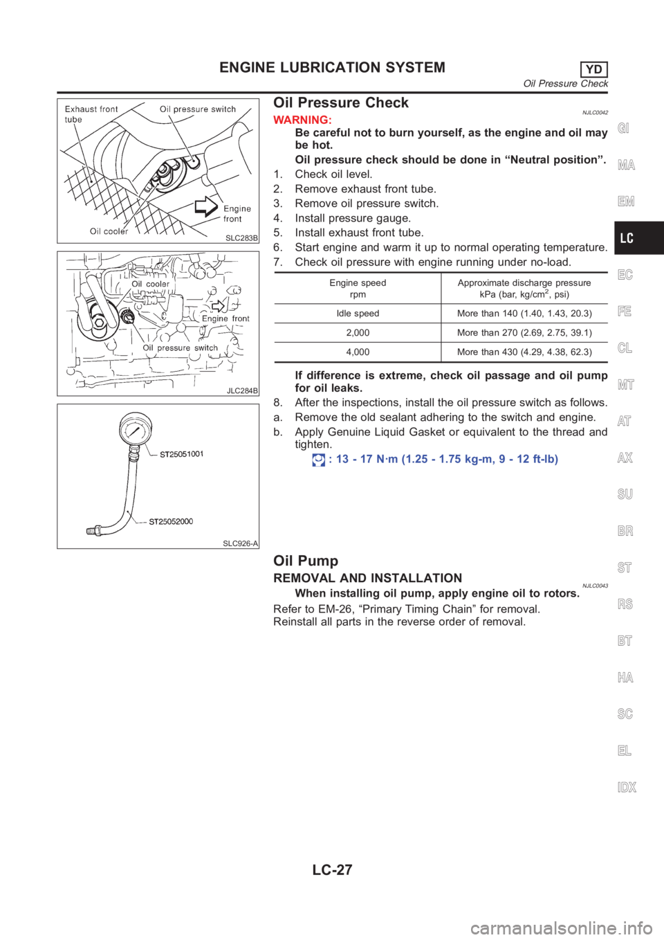
1. Check oil level.
2. Remove exhaust front tube.
3. Remove oil pressure switch.
4. Install pressure gauge.
5. Install exhaust front tube.
6. Start engine and warm it up to normal operating temperature.
7. Check oil pressure with engine running under no-load.
Engine speed
rpmApproximate discharge pressure
kPa (bar, kg/cm2, psi)
Idle speed More than 140 (1.40, 1.43, 20.3)
2,000 More than 270 (2.69, 2.75, 39.1)
4,000 More than 430 (4.29, 4.38, 62.3)
If difference is extreme, check oil passage and oil pump
for oil leaks.
8. After the inspections, install the oil pressure switch as follows.
a. Remove the old sealant adhering to the switch and engine.
b. Apply Genuine Liquid Gasket or equivalent to the thread and
tighten.
: 13 - 17 N·m (1.25 - 1.75 kg-m, 9 - 12 ft-lb)
Oil Pump
REMOVAL AND INSTALLATIONNJLC0043When installing oil pump, apply engine oil to rotors.
Refer to EM-26, “Primary Timing Chain” for removal.
Reinstall all parts in the reverse order of removal.
GI
MA
EM
EC
FE
CL
MT
AT
AX
SU
BR
ST
RS
BT
HA
SC
EL
IDX
ENGINE LUBRICATION SYSTEMYD
Oil Pressure Check
LC-27
Page 316 of 3189
Service Data and Specifications (SDS)
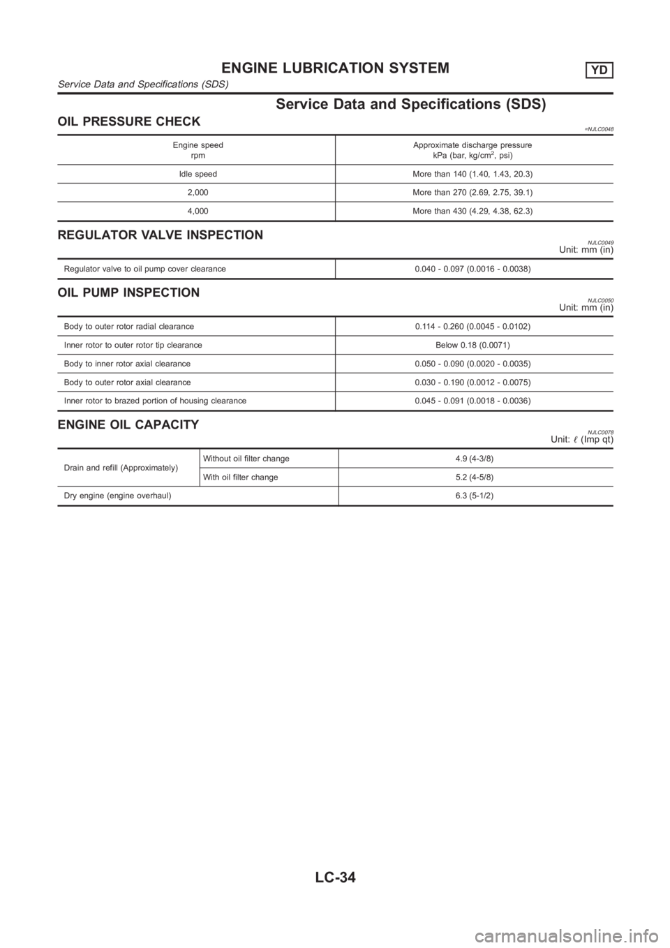
OIL PRESSURE CHECK=NJLC0048
Engine speed
rpmApproximate discharge pressure
kPa (bar, kg/cm2, psi)
Idle speed More than 140 (1.40, 1.43, 20.3)
2,000 More than 270 (2.69, 2.75, 39.1)
4,000 More than 430 (4.29, 4.38, 62.3)
REGULATOR VALVE INSPECTIONNJLC0049Unit: mm (in)
Regulator valve to oil pump cover clearance 0.040 - 0.097 (0.0016 - 0.0038)
OIL PUMP INSPECTIONNJLC0050Unit: mm (in)
Body to outer rotor radial clearance 0.114 - 0.260 (0.0045 - 0.0102)
Inner rotor to outer rotor tip clearance Below 0.18 (0.0071)
Body to inner rotor axial clearance 0.050 - 0.090 (0.0020 - 0.0035)
Body to outer rotor axial clearance 0.030 - 0.190 (0.0012 - 0.0075)
Inner rotor to brazed portion of housing clearance 0.045 - 0.091 (0.0018 - 0.0036)
ENGINE OIL CAPACITYNJLC0078Unit:�(Imp qt)
Drain and refill (Approximately)Without oil filter change 4.9 (4-3/8)
With oil filter change 5.2 (4-5/8)
Dry engine (engine overhaul) <0003000300030003000300030003000300030003000300030003000300030003000300030003000300030003000300030003000300030003000300030003000300030003000300030003000300030003000300030003000300030003000300030003000300
03000300030003000300030003000300030003000300030003[ 6.3 (5-1/2)
ENGINE LUBRICATION SYSTEMYD
Service Data and Specifications (SDS)
LC-34
Page 400 of 3189
![NISSAN ALMERA N16 2003 Electronic Repair Manual EC-70
[QG (WITH EURO-OBD)]
TROUBLE DIAGNOSIS
Symptom Matrix Chart
EBS00K3P
SYSTEM — BASIC ENGINE CONTROL SYSTEM
SYMPTOM
Reference
page
HARD/NO START/RESTART (EXCP. HA)
ENGINE STALL
HESITATION/SURGI](/manual-img/5/57350/w960_57350-399.png "NISSAN ALMERA N16 2003 Electronic Repair Manual EC-70
[QG (WITH EURO-OBD)]
TROUBLE DIAGNOSIS
Symptom Matrix Chart
EBS00K3P
SYSTEM — BASIC ENGINE CONTROL SYSTEM
SYMPTOM
Reference
page
HARD/NO START/RESTART (EXCP. HA)
ENGINE STALL
HESITATION/SURGI")
EC-70
[QG (WITH EURO-OBD)]
TROUBLE DIAGNOSIS
Symptom Matrix Chart
EBS00K3P
SYSTEM — BASIC ENGINE CONTROL SYSTEM
SYMPTOM
Reference
page
HARD/NO START/RESTART (EXCP. HA)
ENGINE STALL
HESITATION/SURGING/FLAT SPOT
SPARK KNOCK/DETONATION
LACK OF POWER/POOR ACCELERATION
HIGH IDLE/LOW IDLE
ROUGH IDLE/HUNTING
IDLING VIBRATION
SLOW/NO RETURN TO IDLE
OVERHEATS/WATER TEMPERATURE HIGH
EXCESSIVE FUEL CONSUMPTION
EXCESSIVE OIL CONSUMPTION
BATTERY DEAD (UNDER CHARGE)
Warranty symptom code AA AB AC AD AE AF AG AH AJ AK AL AM HA
Fuel Fuel pump circuit 11232 22 3 2EC-381
Fuel pressure regulator system334444444 4EC-34
Injector circuit 11232 22 2EC-375
Evaporative emission system 334444444 4EC-251,
EC-399
Air Positive crankcase ventilation sys-
tem334444444 41EC-402
Incorrect idle speed adjustment 33 1111 1EC-65
Electric throttle control actuator 112332222 2 2EC-276
,
EC-278
,
EC-285
,
EC-291
IgnitionIncorrect ignition timing adjustment33111 11 1EC-65
Ignition circuit 11222 22 2EC-365
Main power supply and ground circuit 22333 33 23EC-110
Mass air flow sensor circuit 11222 22 2EC-134
Engine coolant temperature sensor circuit 11222322312EC-144
Throttle position sensor circuit 12 22222 2EC-199
,
EC-205
,
EC-335
,
EC-341
,
EC-343
,
EC-352
Accelerator pedal position sensor circuit3212 2EC-211
,
EC-218
,
EC-345
Heated oxygen sensor 1 circuit 1232 22 2EC-149
,
EC-155
,
EC-165
,
EC-296
,
EC-302
Knock sensor circuit 2 2 3EC-230
Crankshaft position sensor (POS) circuit 2 2EC-234
Camshaft position sensor (PHASE) circuit 2 2EC-240
Vehicle speed signal circuit 2 3 3 3EC-257