2003 NISSAN ALMERA N16 Ignition
[x] Cancel search: IgnitionPage 38 of 3189

NJGI0007
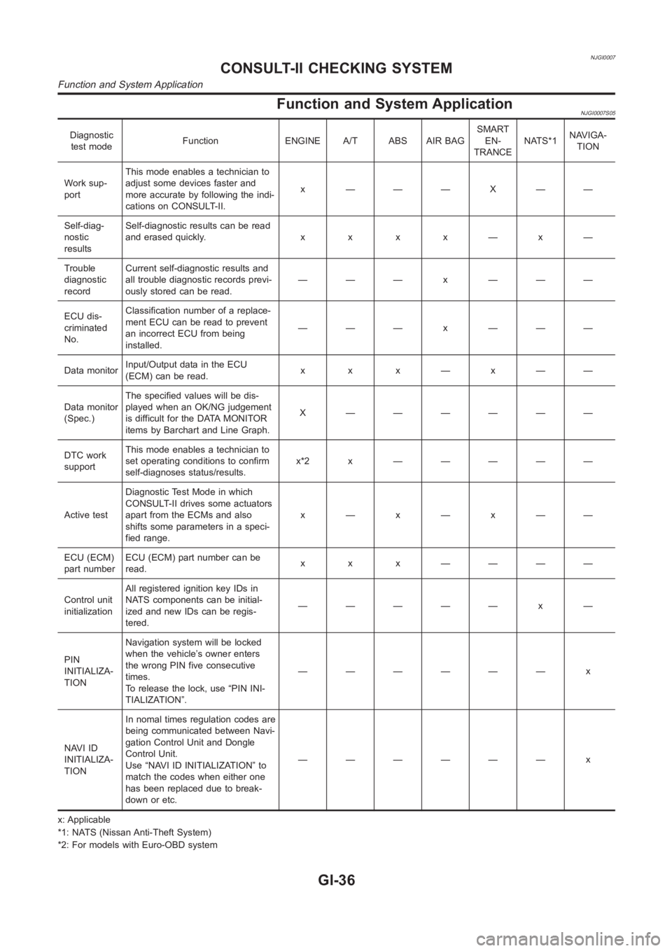
Function and System ApplicationNJGI0007S05
Diagnostic
test modeFunction ENGINE A/T ABS AIR BAGSMART
EN-
TRANCENATS*1NAVIGA-
TION
Work sup-
portThis mode enables a technician to
adjust some devices faster and
more accurate by following the indi-
cations on CONSULT-II.x ———X——
Self-diag-
nostic
resultsSelf-diagnostic results can be read
anderasedquickly. x x x x—x—
Trouble
diagnostic
recordCurrent self-diagnostic results and
all trouble diagnostic records previ-
ously stored can be read.——— x ———
ECU dis-
criminated
No.Classification number of a replace-
ment ECU can be read to prevent
an incorrect ECU from being
installed.——— x ———
Data monitorInput/Output data in the ECU
(ECM) can be read.x x x—x——
Data monitor
(Spec.)The specified values will be dis-
played when an OK/NG judgement
is difficult for the DATA MONITOR
items by Barchart and Line Graph.X ——————
DTC work
supportThis mode enables a technician to
set operating conditions to confirm
self-diagnoses status/results.x*2x —————
Active testDiagnostic Test Mode in which
CONSULT-II drives some actuators
apart from the ECMs and also
shifts some parameters in a speci-
fied range.x—x—x——
ECU (ECM)
part numberECU (ECM) part number can be
read.x x x ————
Control unit
initializationAll registered ignition key IDs in
NATS components can be initial-
ized and new IDs can be regis-
tered.————— x —
PIN
INITIALIZA-
TIONNavigation system will be locked
when the vehicle’s owner enters
the wrong PIN five consecutive
times.
To release the lock, use “PIN INI-
TIALIZATION”.—————— x
NAVI ID
INITIALIZA-
TIONIn nomal times regulation codes are
being communicated between Navi-
gation Control Unit and Dongle
Control Unit.
Use “NAVI ID INITIALIZATION” to
match the codes when either one
has been replaced due to break-
down or etc.—————— x
x: Applicable
*1: NATS (Nissan Anti-Theft System)
*2: For models with Euro-OBD system
CONSULT-II CHECKING SYSTEM
Function and System Application
GI-36
Page 53 of 3189

NJGI0011
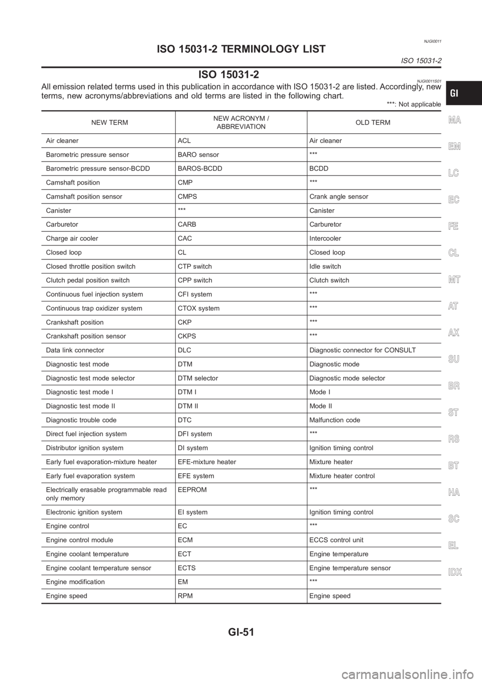
ISO 15031-2NJGI0011S01All emission related terms used in this publication in accordance with ISO15031-2 are listed. Accordingly, new
terms, new acronyms/abbreviations and old terms are listed in the following chart.
***: Not applicable
NEW TERMNEW ACRONYM /
ABBREVIATIONOLD TERM
Air cleaner ACL Air cleaner
Barometric pressure sensor BARO sensor ***
Barometric pressure sensor-BCDD BAROS-BCDD BCDD
Camshaft position CMP ***
Camshaft position sensor CMPS Crank angle sensor
Canister *** Canister
Carburetor CARB Carburetor
Charge air cooler CAC Intercooler
Closed loop CL Closed loop
Closed throttle position switch CTP switch Idle switch
Clutch pedal position switch CPP switch Clutch switch
Continuous fuel injection system CFI system ***
Continuous trap oxidizer system CTOX system ***
Crankshaft position CKP ***
Crankshaft position sensor CKPS ***
Data link connector DLC Diagnostic connector for CONSULT
Diagnostic test mode DTM Diagnostic mode
Diagnostic test mode selector DTM selector Diagnostic mode selector
Diagnostic test mode I DTM I Mode I
Diagnostic test mode II DTM II Mode II
Diagnostic trouble code DTC Malfunction code
Direct fuel injection system DFI system ***
Distributor ignition system DI system Ignition timing control
Early fuel evaporation-mixture heater EFE-mixture heater Mixture heater
Early fuel evaporation system EFE system Mixture heater control
Electrically erasable programmable read
only memoryEEPROM ***
Electronic ignition system EI system Ignition timing control
Engine control EC ***
Engine control module ECM ECCS control unit
Engine coolant temperature ECT Engine temperature
Engine coolant temperature sensor ECTS Engine temperature sensor
Engine modification EM ***
Engine speed RPM Engine speedMA
EM
LC
EC
FE
CL
MT
AT
AX
SU
BR
ST
RS
BT
HA
SC
EL
IDX
ISO 15031-2 TERMINOLOGY LIST
ISO 15031-2
GI-51
Page 54 of 3189

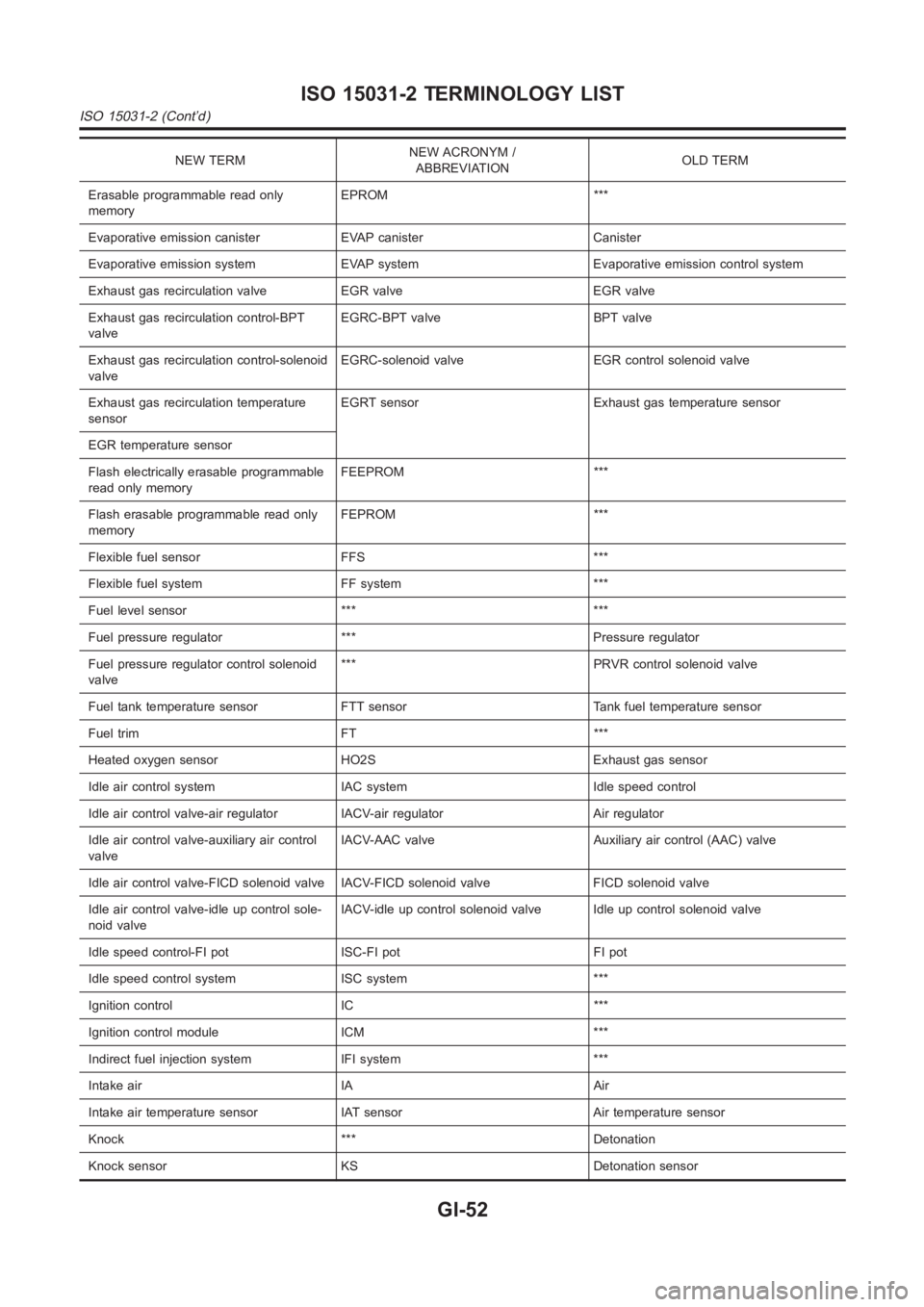
NEW TERMNEW ACRONYM /
ABBREVIATIONOLD TERM
Erasable programmable read only
memoryEPROM ***
Evaporative emission canister EVAP canister Canister
Evaporative emission system EVAP system Evaporative emission control system
Exhaust gas recirculation valve EGR valve EGR valve
Exhaust gas recirculation control-BPT
valveEGRC-BPT valve BPT valve
Exhaust gas recirculation control-solenoid
valveEGRC-solenoid valve EGR control solenoid valve
Exhaust gas recirculation temperature
sensorEGRT sensor Exhaust gas temperature sensor
EGR temperature sensor
Flash electrically erasable programmable
read only memoryFEEPROM ***
Flash erasable programmable read only
memoryFEPROM ***
Flexible fuel sensor FFS ***
Flexible fuel system FF system ***
Fuel level sensor *** ***
Fuel pressure regulator *** Pressure regulator
Fuel pressure regulator control solenoid
valve*** PRVR control solenoid valve
Fuel tank temperature sensor FTT sensor Tank fuel temperature sensor
Fuel trim FT ***
Heated oxygen sensor HO2S Exhaust gas sensor
Idle air control system IAC system Idle speed control
Idle air control valve-air regulator IACV-air regulator Air regulator
Idle air control valve-auxiliary air control
valveIACV-AAC valve Auxiliary air control (AAC) valve
Idle air control valve-FICD solenoid valve IACV-FICD solenoid valve FICDsolenoid valve
Idle air control valve-idle up control sole-
noid valveIACV-idle up control solenoid valve Idle up control solenoid valve
Idle speed control-FI pot ISC-FI pot FI pot
Idle speed control system ISC system ***
Ignition control IC ***
Ignition control module ICM ***
Indirect fuel injection system IFI system ***
Intake air IA Air
Intake air temperature sensor IAT sensor Air temperature sensor
Knock *** Detonation
Knock sensor KS Detonation sensor
ISO 15031-2 TERMINOLOGY LIST
ISO 15031-2 (Cont’d)
GI-52
Page 79 of 3189

EM-1
ENGINE MECHANICAL
B ENGINE
CONTENTS
C
D
E
F
G
H
I
J
K
L
M
SECTION
A
EM
ENGINE MECHANICAL
QG
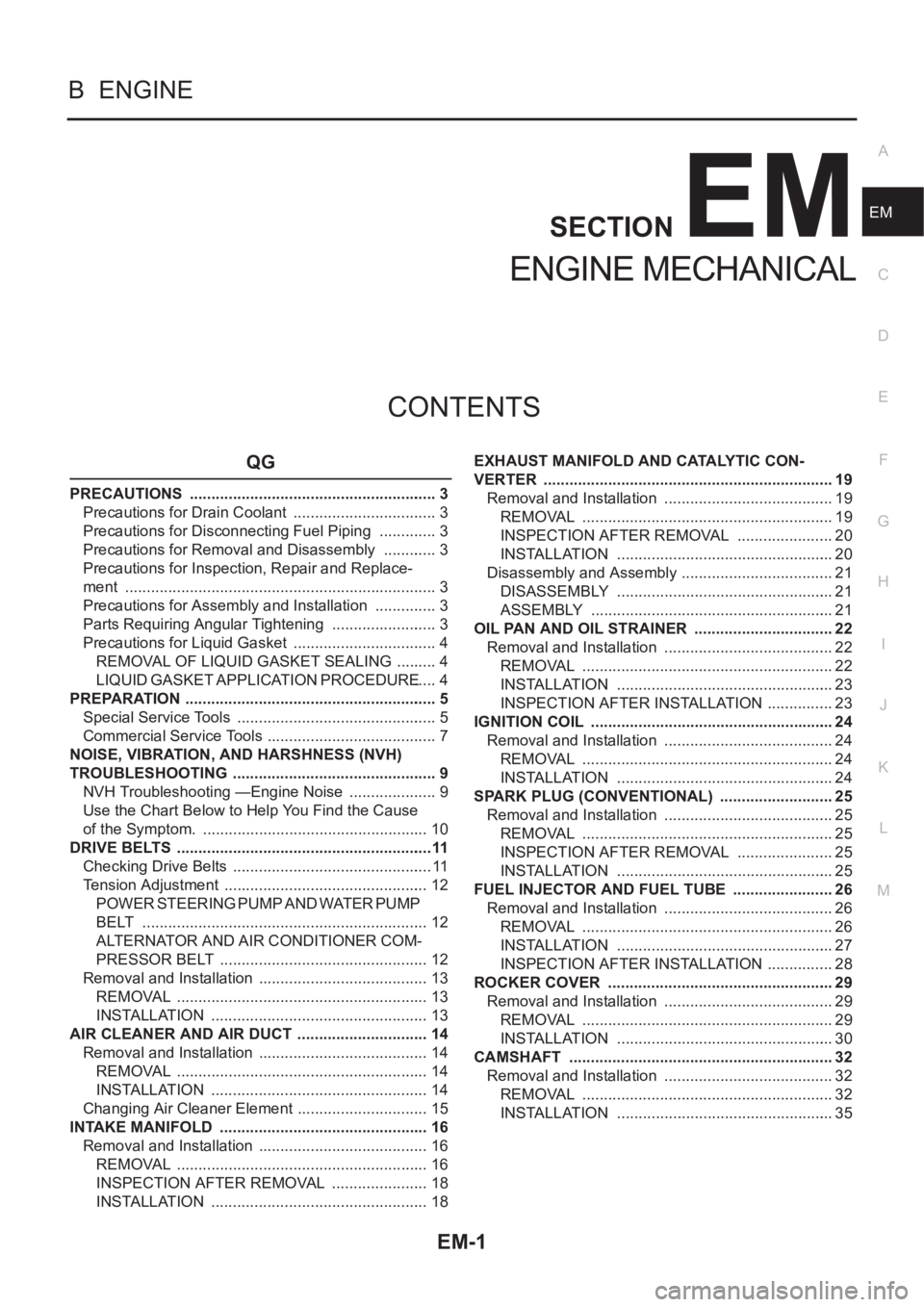
PRECAUTIONS .......................................................... 3
Precautions for Drain Coolant .................................. 3
Precautions for Disconnecting Fuel Piping .............. 3
Precautions for Removal and Disassembly ............. 3
Precautions for Inspection, Repair and Replace-
ment ......................................................................... 3
Precautions for Assembly and Installation ............... 3
Parts Requiring Angular Tightening ......................... 3
Precautions for Liquid Gasket .................................. 4
REMOVAL OF LIQUID GASKET SEALING .......... 4
LIQUID GASKET APPLICATION PROCEDURE ..... 4
PREPARATION ........................................................... 5
Special Service Tools ............................................... 5
Commercial Service Tools ........................................ 7
NOISE, VIBRATION, AND HARSHNESS (NVH)
TROUBLESHOOTING ................................................ 9
NVH Troubleshooting —Engine Noise ..................... 9
Use the Chart Below to Help You Find the Cause
of the Symptom. ..................................................... 10
DRIVE BELTS ............................................................11
Checking Drive Belts ............................................... 11
Tension Adjustment ................................................ 12
POWER STEERING PUMP AND WATER PUMP
BELT ................................................................... 12
ALTERNATOR AND AIR CONDITIONER COM-
PRESSOR BELT ................................................. 12
Removal and Installation ........................................ 13
REMOVAL ........................................................... 13
INSTALLATION ................................................... 13
AIR CLEANER AND AIR DUCT ............................... 14
Removal and Installation ........................................ 14
REMOVAL ........................................................... 14
INSTALLATION ................................................... 14
Changing Air Cleaner Element ............................... 15
INTAKE MANIFOLD ................................................. 16
Removal and Installation ........................................ 16
REMOVAL ........................................................... 16
INSPECTION AFTER REMOVAL ....................... 18
INSTALLATION ................................................... 18EXHAUST MANIFOLD AND CATALYTIC CON-
VERTER .................................................................... 19
Removal and Installation ........................................ 19
REMOVAL ........................................................... 19
INSPECTION AFTER REMOVAL ....................... 20
INSTALLATION ................................................... 20
Disassembly and Assembly .................................... 21
DISASSEMBLY ................................................... 21
ASSEMBLY ......................................................... 21
OIL PAN AND OIL STRAINER ..............................
... 22
Removal and Installation ........................................ 22
REMOVAL ........................................................... 22
INSTALLATION ................................................... 23
INSPECTION AFTER INSTALLATION ................ 23
IGNITION COIL ......................................................... 24
Removal and Installation ........................................ 24
REMOVAL ........................................................... 24
INSTALLATION ................................................... 24
SPARK PLUG (CONVENTIONAL) ........................... 25
Removal and Installation ........................................ 25
REMOVAL ........................................................... 25
INSPECTION AFTER REMOVAL ....................... 25
INSTALLATION ................................................... 25
FUEL INJECTOR AND FUEL TUBE ........................ 26
Removal and Installation ........................................ 26
REMOVAL ........................................................... 26
INSTALLATION ................................................... 27
INSPECTION AFTER INSTALLATION ................ 28
ROCKER COVER ..................................................... 29
Removal and Installation ........................................ 29
REMOVAL ........................................................... 29
INSTALLATION ................................................... 30
CAMSHAFT .............................................................. 32
Removal and Installation ........................................ 32
REMOVAL ........................................................... 32
INSTALLATION ................................................... 35
Page 102 of 3189
![NISSAN ALMERA N16 2003 Electronic Repair Manual EM-24
[QG]
IGNITION COIL
IGNITION COIL
PFP:22448
Removal and InstallationEBS00LQ7
REMOVAL
1. Remove ignition coil harness connector from ignition coil.
2. Remove ignition coil.
CAUTION:
●Do not shoc NISSAN ALMERA N16 2003 Electronic Repair Manual EM-24
[QG]
IGNITION COIL
IGNITION COIL
PFP:22448
Removal and InstallationEBS00LQ7
REMOVAL
1. Remove ignition coil harness connector from ignition coil.
2. Remove ignition coil.
CAUTION:
●Do not shoc](/manual-img/5/57350/w960_57350-101.png)
EM-24
[QG]
IGNITION COIL
IGNITION COIL
PFP:22448
Removal and InstallationEBS00LQ7
REMOVAL
1. Remove ignition coil harness connector from ignition coil.
2. Remove ignition coil.
CAUTION:
●Do not shock it.
●Do not disassemble it.
INSTALLATION
●Install in the reverse order of removal.
YEM050
1. Ignition coil 2. Spark plug 3. Rocker cover
Page 103 of 3189
![NISSAN ALMERA N16 2003 Electronic Repair Manual SPARK PLUG (CONVENTIONAL)
EM-25
[QG]
C
D
E
F
G
H
I
J
K
L
MA
EM
SPARK PLUG (CONVENTIONAL)PFP:22401
Removal and InstallationEBS00LQ8
REMOVAL
1. Disconnect ignition coil harness connector from ignition c NISSAN ALMERA N16 2003 Electronic Repair Manual SPARK PLUG (CONVENTIONAL)
EM-25
[QG]
C
D
E
F
G
H
I
J
K
L
MA
EM
SPARK PLUG (CONVENTIONAL)PFP:22401
Removal and InstallationEBS00LQ8
REMOVAL
1. Disconnect ignition coil harness connector from ignition c](/manual-img/5/57350/w960_57350-102.png)
SPARK PLUG (CONVENTIONAL)
EM-25
[QG]
C
D
E
F
G
H
I
J
K
L
MA
EM
SPARK PLUG (CONVENTIONAL)PFP:22401
Removal and InstallationEBS00LQ8
REMOVAL
1. Disconnect ignition coil harness connector from ignition coil.
2. Remove ignition coil.
3. Remove spark plugs with a spark plug wrench (commercial ser-
vice tool).
Spark plug
INSPECTION AFTER REMOVAL
Check spark plug gap. Adjust or replace if necessary.
●Use a wire brush for cleaning, if necessary.
INSTALLATION
Install in the reverse order of removal, paying attention to the following.
Make NGK Champion
Standard type LFR5A-11 REC10YC4
Hot type LFR4A-11 —
Cold type LFR6A-11 —
SMA581C
Standard : 1.0 - 1.1 mm (0.039 - 0.043 in)
SMA476
Spark plug:
: 19.6 - 29.4 N·m (2.0 - 3.0 kg-m, 15 - 21 ft-lb)
Page 106 of 3189
![NISSAN ALMERA N16 2003 Electronic Repair Manual EM-28
[QG]
FUEL INJECTOR AND FUEL TUBE
3. Tighten mounting bolts in two steps in numerical order shown in
figure.
4. Install fuel feed hose.
CAUTION:
Install hose clamp avoiding interference with NISSAN ALMERA N16 2003 Electronic Repair Manual EM-28
[QG]
FUEL INJECTOR AND FUEL TUBE
3. Tighten mounting bolts in two steps in numerical order shown in
figure.
4. Install fuel feed hose.
CAUTION:
Install hose clamp avoiding interference with](/manual-img/5/57350/w960_57350-105.png)
EM-28
[QG]
FUEL INJECTOR AND FUEL TUBE
3. Tighten mounting bolts in two steps in numerical order shown in
figure.
4. Install fuel feed hose.
CAUTION:
Install hose clamp avoiding interference with bulge, and
securely tighten it
5. Install remaining parts in the reverse order of removal.
INSPECTION AFTER INSTALLATION
●Check for fuel leakage with following procedure.
1. Turn ignition switch ON (do not start engine), and check connections for leakage by applying fuel pressure
to fuel piping.
2. Start engine, and re-check connections for fuel leakage by increasing engine speed. 1st step : 11.8 - 13.8 N·m (1.2 - 1.4 kg-m, 9 - 10 ft-lb)
2nd step : 17 - 23 N·m (1.7 - 2.4 kg-m, 13 - 17 ft-lb)
PBIC0617E
Page 107 of 3189
![NISSAN ALMERA N16 2003 Electronic Repair Manual ROCKER COVER
EM-29
[QG]
C
D
E
F
G
H
I
J
K
L
MA
EM
ROCKER COVERPFP:13264
Removal and InstallationEBS00LQA
CAUTION:
Apply new engine oil when installing the parts that specified to do so in the figure.
NISSAN ALMERA N16 2003 Electronic Repair Manual ROCKER COVER
EM-29
[QG]
C
D
E
F
G
H
I
J
K
L
MA
EM
ROCKER COVERPFP:13264
Removal and InstallationEBS00LQA
CAUTION:
Apply new engine oil when installing the parts that specified to do so in the figure.](/manual-img/5/57350/w960_57350-106.png)
ROCKER COVER
EM-29
[QG]
C
D
E
F
G
H
I
J
K
L
MA
EM
ROCKER COVERPFP:13264
Removal and InstallationEBS00LQA
CAUTION:
Apply new engine oil when installing the parts that specified to do so in the figure.
REMOVAL
1. Move harnesses on top surface and right side of rocker cover, and move them aside.
2. Remove ignition coil. Refer to EM-24, "
Removal and Installation" .
3. Disconnect PCV hoses on rocker cover side.
4. If necessary, remove PCV control valve.
5. If necessary, remove intake valve timing control solenoid valve and camshaft position sensor (PHASE).
CAUTION:
●Do not shock it.
●Do not disassemble it.
●Tip of camshaft position sensor (PHASE) generates strong magnetic fields. Keep it away from
metal particles or objects affected by magnetic fields.
KBIA1375E
1. PCV hose 2. Rocker cover 3. Grommet
4. PCV control valve 5. PCV hose 6.Intake valve timing control solenoid
valve
7. O-ring 8. Oil filter cap 9. Gasket
10. Gasket 11. Rocker cover oil seal 12. Gasket
13. O-ring 14. Camshaft position sensor (PHASE)