Page 424 of 1000
AC204182
CONNECTOR : I-03
AK
I-03(B)
1
HARNESS
SIDE
I-03(B)
AC204191
JUNCTION BLOCK
(FRONT VIEW)
AC204191
CONNECTORS : D-216, D-217
D-217
D-216 RELAY SIDE
D-216
D-217 HARNESS SIDE
BA
8 1
11 103 4
12
9 2
13 146
5
157
1 2
5 4 3
AC204171
CONNECTOR : D-111
AQ
9 8
67
5 34
20
3221
33
43 1718
30
41 16
29 28
39 40 13
25 12
24
35 3614
26
3715
27
3819
31
42 1
10
222
11
23
34
Page 425 of 1000
AC204170
CONNECTOR : D-23
D-23(B)
D-23(B)
CP
HARNESS
SIDE
1 3 42
12 14 13 11 6 7 8 10 9
18
19 2016 175
15
AC204173
CONNECTOR : D-216
BD
JUNCTION BLOCK
SIDE
1 2
5 4 3
Page 426 of 1000
AC204170
CONNECTOR : D-23
D-23(B)
D-23(B)
CP
HARNESS
SIDE
1 3 42
12 14 13 11 6 7 8 10 9
18
19 2016 175
15
AC204191
JUNCTION BLOCK
(FRONT VIEW)
CONNECTORS : D-209, D-216
D-209 HARNESS SIDE
D-216 RELAY SIDE
AX
D-209
D-216
1 2
5 4 3
1 2
6 7 9 3 4
11 12
10 5
13 8
Page 451 of 1000
Lock Sensor Circuit
AC204169
CONNECTOR : B-30
AF
B-30(B)
AC204170
CONNECTORS : D-23, D-24
DV
D-24(B)
D-23(B)
AC204176BM
CONNECTOR : E-111
Page 483 of 1000

AC106603
Indicates power source.
Indicates that terminal is conne-
cted via a plate in the relay box.
Each circuit diagram consists of
block(s). The blocks are divided
by page number.
Indicates splice point numbers.
These numbers are identical to
those described in "Splice Loca-
tions."
Indicates the circuit name to be
connected. The arrow indicates
the current flow direction.
Indicates the power supply in
the control unit. If no voltage is
displayed, this indicates battery
positive voltage.
An "X" at the end of a connector
number indicates that the conn-
ector is connected to a central-
ized junction that is shown in the
section "Centralized Junction."
Indicates the connector symbol.
Connectors in the circuit diagram
are indicated in numerical order.
Indicates the operating conditions
of the engine coolant switch, etc.
Indicates connector number.
The same number as used in the
wiring harness diagram.
Connector and connector numbers
are shown at the lower part of the
page.
Connector numbers not enclosed
by frame indicate the device incor-
porated into wiring harness.
Indicates the circuit mame
to be connected. The arrow
indicatesthe current flow
direction.
Indicates that the diagram contin-
ues at which belongs to the
block in the same circuit.
AB
Indicates shield wire.Indicates that current
flows upwards.
Page 484 of 1000

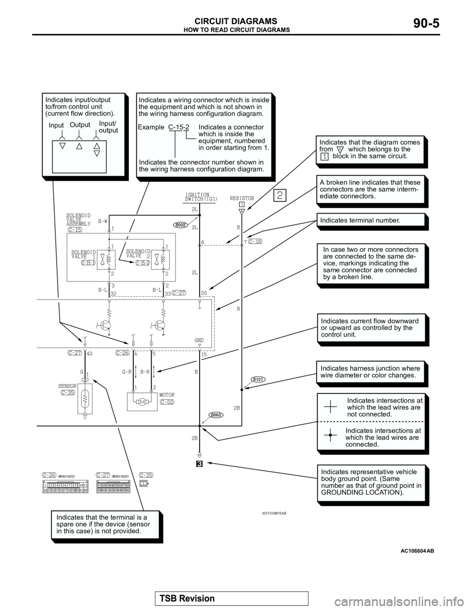
AC106604
Indicates that the terminal is a
spare one if the device (sensor
in this case) is not provided.
Indicates representative vehicle
body ground point. (Same
number as that of ground point in
GROUNDING LOCATION).
Indicates harness junction where
wire diameter or color changes.
In case two or more connectors
are connected to the same de-
vice, markings indicating the
same connector are connected
by a broken line.
Indicates terminal number.
A broken line indicates that these
connectors are the same interm-
ediate connectors.
Indicates intersections at
which the lead wires are
not connected.
Indicates intersections at
which the lead wires are
connected.
Indicates input/output
to/from control unit
(current flow direction).
InputOutputInput/
output
Indicates current flow downward
or upward as controlled by the
control unit.
AB
Indicates that the diagram comes
from which belongs to the
block in the same circuit.
Indicates a wiring connector which is inside
the equipment and which is not shown in
the wiring harness configuration diagram.
Example C-15-2
Indicates a connector
which is inside the
equipment, numbered
in order starting from 1.
Indicates the connector number shown in
the wiring harness configuration diagram.
Page 503 of 1000
AC203972
17
18 19
20
(IN JUNCTION BLOCK)
AB
1 23456 78
11
13 14 15
9
1612
10
Page 788 of 1000
CAUTION
ACX00751ABINDICATOR MARKA
ACX01424 AB
HOLE A HOLE B
SQUARE
HOLECLOCKWISE
ALLEN WRENCH