Page 189 of 304

189 Operation
Vehicle care
Engine cleaning
Prior to cleaning the engine compartment,
make sure to protect electrical compo-
nents and connectors from contact with
water and cleaning agents.
Corrosion protection, such as MB Anticor-
rosion Wax should be applied to the engine
compartment after every engine cleaning.
Before applying, all control linkage bush-
ings and joints should be lubricated. The
poly-V-belt and all pulleys should be pro-
tected from any wax. Vehicle washing
Do not use hot water or wash your vehicle
in direct sunlight. Use only a mild car wash
detergent, such as Mercedes-Benz ap-
proved Car Shampoo.
Thoroughly spray the vehicle with a dif-
fused jet of water. Direct only a very weak
spray towards the ventilation intake. Use
plenty of water and rinse the sponge and
chamois frequently.
Rinse with clear water and thoroughly dry
with a chamois. Do not allow cleaning
agents to dry on the finish.
Due to the width of the vehicle, fold in out-
side mirrors prior to running the vehicle
through an automatic car wash to prevent
damage to the mirrors.
In the winter, thoroughly remove all traces
of road salt as soon as possible.
When washing the underbody, do not for-
get to clean the inner sides of the wheels.Ornamental moldings
For regular cleaning and care of very dirty
chrome-plated parts, use a chrome clean-
er.
Headlamps, tail lamps, turn signal
lenses
Use a mild car wash detergent, such as
Mercedes-Benz approved Car Shampoo,
with plenty of water.
To prevent scratches, never apply strong
force and use only a soft, non-scratchy
cloth when cleaning the lenses. Do not at-
tempt to wipe dirty lenses with a dry cloth
or sponge.
Page 193 of 304
193 Practical hints
What to do if …?
Where will I find ...?
Unlocking/locking in an emergency
Opening/closing in an emergency
Replacing bulbs
Replacing wiper blades
Flat tire
Battery
Jump starting
Towing the vehicle
Fuses
Page 206 of 304

206 Practical hintsWhere will I find ...?
Where will I find ...?First aid kit
The first aid kit is located on the left side of
the trunk.
1First aid kit�
Loosen the fastening strap.
�
Remove first aid kit1.
Vehicle tool kit
The following is included:�
Vehicle tool kit
�
Towing eye bolt
�
Wheel wrench
�
Alignment bolt
�
Vehicle jack
�
Wheel bolts
�
Special fuse puller
The jack is exclusively designed for lifting
the vehicle during a wheel change. Always
lower the vehicle on sufficient capacity
jackstands before working under the
vehicle.
iCheck expiration dates and contents
for completeness at least once a year
and replace missing/expired items.
Warning!
G
The jack is designed exclusively for jacking
up the vehicle at the jack tubes built into ei-
ther side of the vehicle. To help avoid per-
sonal injury, use the jack only to lift the
vehicle during a wheel change. Never get
beneath the vehicle while it is supported by
the jack. Keep hands and feet away from the
area under the lifted vehicle. Always firmly
set parking brake and block wheels before
raising vehicle with jack.
Do not disengage parking brake while the
vehicle is raised. Be certain that the jack is
always vertical (plumb line) when in use, es-
pecially on hills. Always try to use the jack
on level surface. Be sure that the jack arm is
fully inserted in the jack tube. Always lower
the vehicle onto sufficient capacity jack-
stands before working under the vehicle.
Page 214 of 304
214 Practical hintsUnlocking/locking in an emergencyManually unlocking the transmission selector lever
In the case of power failure, the transmis-
sion selector lever can be manually un-
locked, e.g. to tow the vehicle.
1Pin�
Insert a pin1, e.g. ball point pen, into
the covered opening below positionD
of the shift pattern.
�
Perform the following two steps simul-
taneously:�
Push pin1 down.
�
Move selector lever from
positionP.
�
Remove pin1.iAfter removing the pin from the open-
ing, the cover will not close fully. Only
after moving the selector lever to
positionsD+ andD- does the cover re-
turn to its closed position.
The selector lever is locked again when
moving it to positionP.
Page 224 of 304
224 Practical hintsReplacing bulbsParking, standing and turn signal lamp�
Switch off the lights.
�
Open the hood (
�page 171).
1Release opening
�
Insert the screwdriver from the vehicle
tool kit into release opening1.
�
Press the top of the screwdriver toward
the middle of the vehicle and toward
the rear.
The turn signal lamp will be lifted out.
�
Pull the turn signal lamp slightly out of
its mounting.
�
Pull off the electrical connector from
the turn signal lamp.
You can now take the turn signal lamp
completely out of its mounting.
�
Twist bulb socket counterclockwise
and pull out.
�
Gently push bulb into socket, turn
counterclockwise and remove.
�
Insert new bulb in socket, push in and
twist clockwise.
�
Reinstall bulb socket, push in and twist
clockwise.
�
Plug electrical connector back into the
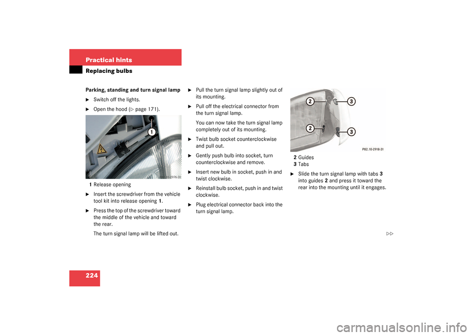
turn signal lamp.2Guides
3Tabs
�
Slide the turn signal lamp with tabs3
into guides2 and press it toward the
rear into the mounting until it engages.
��
Page 225 of 304

225 Practical hints
Replacing bulbs
Side marker lamp bulb�
Switch off the lights.
�
Carefully slide lamp towards front.
�
Remove rear end first.
�
Twist bulb socket counterclockwise
and pull out.
�
Gently push bulb into socket, turn
counterclockwise and remove.
�
Insert new bulb in socket, push in and
twist clockwise.
�
Reinstall bulb socket, push in and twist
clockwise.
�
To reinstall lamp, set rear end in
bumper and let front end snap into
place.
Replacing bulbs for rear lamps
Tail lamp assemblies
1Brake lamp
2Turn signal lamp
3Tail, parking and standing lamp, side
marker
4Backup lamp
5Rear fog lamp (driver’s side)
�
Switch off the lights.
�
Open trunk lid (
�page 77).
�
Remove cover in right side panel.
�
Remove first aid kit (
�page 206).
Remove cover in left side panel.
�
Turn bulb socket counterclockwise and
pull out.
�
Gently push bulb into socket, turn
counterclockwise and remove.
�
Insert new bulb in socket, push in and
turn clockwise.
�
Reinstall bulb socket, push in and turn
clockwise.
�
Close cover.
Page 244 of 304

244 Practical hintsFlat tire
�
Detach the electric air pump.
�
Reinstall tire valve cap.
�
Stow the electrical plug and the air
hose behind the flap and place the air
pump back in the trunk.
�
Close the trunk lid.Storing collapsible spare wheel in
wheel well
Before you can store the spare wheel with
collapsible tire in the wheel well you have
to release the air pressure of the tire.
�
Unscrew valve stem removal tool,
which is part of the valve cap, from tire
valve.
�
Using the valve stem removal tool,
open tire valve slightly by turning the
tire valve insert counterclockwise to
release air pressure.
�
When the air pressure has been re-
leased, remove tire valve insert (pro-
tect it from dirt and sand) using the
previously removed tire valve cap.
�
Once all air is out of the tire, and the
tire has collapsed to its original shape,
reinstall the tire valve insert and valve
cap.
�
Place spare wheel in wheel well and
secure it with the pump holder.
�
Tu rn pu m p hold er cl ockwi se to its st op.
Warning!
G
Follow recommend inflation pressures.
Do not overinflate tires. Overinflating tires
can result in sudden deflation (blowout) be-
cause they are more likely to become punc-
tured or damaged by road debris, potholes
etc.
Do not underinflate tires. Underinflated tires
wear unevenly, adversely affect handling
and fuel economy, and are more likely to fail
from being overheated.
Do not overload the tires by exceeding the
specified vehicle capacity weight (as indicat-
ed by the label on the pillar in the driver’s
door opening). Overloading the tires can
overheat them, possibly causing a blowout.
Warning!
G
To prevent possible injury when unscrewing
air pump filler hose from tire valve after in-
flating the tire, use a rag since the tire valve
could be hot.
Page 248 of 304

248 Practical hintsJump startingThe battery is located in the engine com-
partment on the right hand side.�
Make sure that the two vehicles do not
touch.
�
Turn off all electrical consumers, ex-
cept hazard warning flashers or work
lights.
�
Apply parking brake.
�
Shift selector lever to positionP (man-
ual transmission to Neutral).1Positive terminal of charged battery
2Positive terminal of discharged battery
3Negative terminal of discharged
battery
4Negative terminal of charged battery
�
Connect positive terminals1 and2 of
the batteries with the jumper cables.
Clamp cable to charged battery1 first.
�
Start engine of the vehicle with the
charged battery and run at idle speed.
�
Connect negative terminals3 and4 of
the batteries with the jumper cables.
Clamp cable to charged battery4 first.
�
Start the engine of the disabled vehi-
cle.
Now you can again turn on the electrical
consumers. Do not turn on the lights under
any circumstances.
�
Remove the jumper cables first from
negative terminals3 and4 of the bat-
teries and then from positive
terminals1 and2.
�
Have the battery checked at the near-
est authorized Mercedes-Benz Center.
Warning!
G
Keep flames or sparks away from battery.
Do not smoke.
Observe all safety instructions and precau-
tions when handling automotive batteries.
iVehicles with automatic transmission:
Do not tow-start vehicle.