Page 217 of 304
217 Practical hints
Opening/closing in an emergency
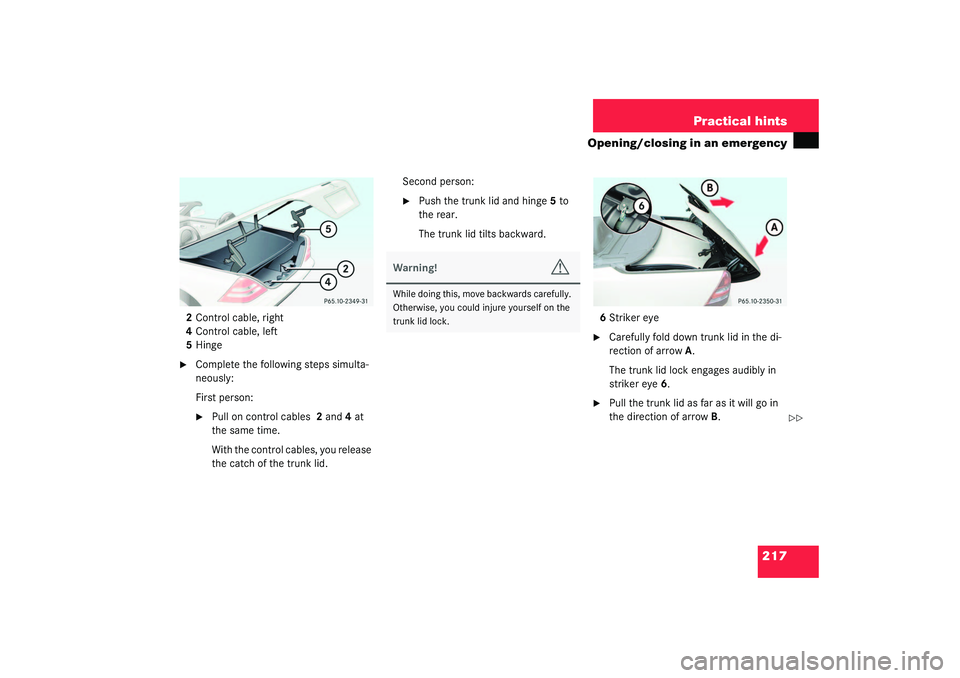
2Control cable, right
4Control cable, left
5Hinge�
Complete the following steps simulta-
neously:
First person:�
Pull on control cables 2 and4 at
the same time.
With the control cables, you release
the catch of the trunk lid.Second person:
�
Push the trunk lid and hinge5 to
the rear.
The trunk lid tilts backward.
6Striker eye
�
Carefully fold down trunk lid in the di-
rection of arrowA.
The trunk lid lock engages audibly in
striker eye6.
�
Pull the trunk lid as far as it will go in
the direction of arrowB.
��
Warning!
G
While doing this, move backwards carefully.
Otherwise, you could injure yourself on the
trunk lid lock.
Page 243 of 304

243 Practical hints
Flat tire
�
Before storing the jack in the trunk, it
should be fully collapsed, with pin and
handle folded in.
Inflating the collapsible spare tire
�
Take the electric air pump out of the
trunk (
�page 207).
1Flap
2Air hose with pressure gauge and vent
screw
3Union nut
4Electrical plug
�
Open flap1 on air pump.
�
Pull out electrical plug4 and air hose
with pressure gauge2.
�
Unscrew valve cap from spare wheel
tire valve.
�
Screw union nut3 with air hose2 on to
the tire valve.
�
Insert electrical plug4 into vehicle
cigarette lighter socket.
�
Turn key in steering lock to position1
(�page 29).
�
PressI on the electric air pump switch.
The electric air pump should now
switch on and inflate the tire.
�
Inflate the collapsible tire to around
36 psi (2.5 bar).This takes about 5 minutes for the col-
lapsible spare tire. Airhose2 and union
nut3 can become hot duration infla-
tion.
�
Press0 on the electric air pump
switch.
The electric air pump should now be
switched off.
�
Turn key in steering lock to position0.
�
If the tire pressure is above 36 psi
(2.5 bar) release excess tire pressure
using the vent screw.
Warning!
G
Observe instructions on air pump label.
!Do not operate the electric air pump
longer than 8 minutes without interrup-
tion. Otherwise it may overheat.
You may operate the air pump again af-
ter it has cooled off.
��
Page 244 of 304

244 Practical hintsFlat tire
�
Detach the electric air pump.
�
Reinstall tire valve cap.
�
Stow the electrical plug and the air
hose behind the flap and place the air
pump back in the trunk.
�
Close the trunk lid.Storing collapsible spare wheel in
wheel well
Before you can store the spare wheel with
collapsible tire in the wheel well you have
to release the air pressure of the tire.
�
Unscrew valve stem removal tool,
which is part of the valve cap, from tire
valve.
�
Using the valve stem removal tool,
open tire valve slightly by turning the
tire valve insert counterclockwise to
release air pressure.
�
When the air pressure has been re-
leased, remove tire valve insert (pro-
tect it from dirt and sand) using the
previously removed tire valve cap.
�
Once all air is out of the tire, and the
tire has collapsed to its original shape,
reinstall the tire valve insert and valve
cap.
�
Place spare wheel in wheel well and
secure it with the pump holder.
�
Tu rn pu m p hold er cl ockwi se to its st op.
Warning!
G
Follow recommend inflation pressures.
Do not overinflate tires. Overinflating tires
can result in sudden deflation (blowout) be-
cause they are more likely to become punc-
tured or damaged by road debris, potholes
etc.
Do not underinflate tires. Underinflated tires
wear unevenly, adversely affect handling
and fuel economy, and are more likely to fail
from being overheated.
Do not overload the tires by exceeding the
specified vehicle capacity weight (as indicat-
ed by the label on the pillar in the driver’s
door opening). Overloading the tires can
overheat them, possibly causing a blowout.
Warning!
G
To prevent possible injury when unscrewing
air pump filler hose from tire valve after in-
flating the tire, use a rag since the tire valve
could be hot.
Page 253 of 304
253 Practical hintsFuses
Fuses
A special fuse extractor is supplied with
the vehicle tool kit in the trunk.
Spare fuses are supplied inside the corre-
sponding fuse box.
The fuse chart is printed on the cover of
the corresponding fuse box.
The amperages of the fuses are also given
there.
Main fuse box
The main fuse box is located in the engine
compartment on the left hand side.
The main fuse box contains fuses for
interior consumers.
1Main fuse boxOpening
�
Release clamp (arrow) and lift fuse box
cover1.
�
Remove fuse box cover.
Closing
�
Fit fuse box cover1 back into the rear
clamp.
�
Close fuse box cover until the clamp
engages.
iOnly install fuses that have been tested
and approved by Mercedes-Benz and
that have the specified amperage rat-
ing.
Never attempt to repair or bridge a
blown fuse. Have the cause determined
and remedied by an authorized
Mercedes-Benz Center.
Page 290 of 304
 98
Emergency operations
Closing hardtop 215
Opening hardtop 215
Remote door unlock 151")
290 IndexEmergency calls
Initiating an emergency call 147
With Tele Aid 146
Emergency operation (Limp Home
Mode) 98
Emergency operations
Closing hardtop 215
Opening hardtop 215
Remote door unlock 151
Unlocking the vehicle 210
Emergency release for trunk lid 78
Emergency tensioning device see
ETD 60, 280
Emission control 167
Emission control label 258
Engine
Compartment 171
Starting with automatic
transmission* 41
Starting with manual
transmission 40
Starting with the key 40, 41
Technical data 260
Turning off with the key 48
Engine cleaning 189
Engine compartment 171Hood 171
Engine malfunction indicator lamp 21,
199
Engine number 280
Engine oil 172, 271
Adding 175
Additives 271
Checking level 172
Consumption 172
Filler neck 175
Viscosity 280
Engine oil level see Oil level 170
ESP 22, 68, 280
Switching off 70
Switching on 70
Warning lamp 194
ETD 280
Safety guidelines 55
ETD (Emergency tensioning device) 60
Exterior lamp switch 83
Exterior rear view mirrors
Adjusting 35
F
Fastening the seat belts 37
Fine adjustment
Cruise control 138First aid kit 206
Flat tire 229
Lowering the vehicle 242
Mounting the spare wheel 238
Preparing the vehicle 229
Spare wheel 207
TIREFIT 208, 209
Flexible Service System (FSS) 185, 280
Fog lamp, rear 84, 222
Fog lamps
Replacing bulbs 221
Fog lamps, front
Replacing bulbs 222
Switching on 84
Front airbags 56
Front lamps
Replacing bulbs 221, 223
Switching on 83
Front seats
Heater* 81
FSS (Flexible Service System) 185, 280
Page 300 of 304

300 IndexTrunk lid emergency release 78
Trunk see Cargo compartment 77
Turn signal lamps
Replacing bulbs 221, 222
Turn signals 43
Additional in mirrors 221
Cleaning lenses 189
Front bulbs 221, 224
Indicator lamps 21
Rear bulbs 222, 225
Turning off
Engine 48
U
Unlocking 28, 74
Centrally from inside 80
Driver’s door in an emergency 210
Fuel filler flap 169
Global 75
In an emergency 210
Selective settings 75
Transmission selector lever
manually 214
Trunk in an emergency 210
Vehicle in an emergency 151
With the remote control 28
Upgrade signalsTele Aid 150
Uphill driving
Cruise control 137
Upshifting 94
Useful features 139
Ashtray 142
Cigarette lighter 143
Garage door opener 152
Interior storage spaces 139
Tele Aid 144
Telephone* 143
V
Vehicle
Battery 245
Locking 23
Lowering 242
Proper use of 14
Towing 249, 251, 252
Unlocking 23
Unlocking in an emergency 210
Vehicle battery 245
Vehicle care 187
Cloth upholstery 192
Cup holder 191
Engine cleaning 189
Gear selector lever 191Hard plastic trim items 191
Headlamps 189
Instrument cluster 191
Leather upholstery 192
Light alloy wheels 191
Ornamental moldings 189
Paintwork 188
Plastic and rubber parts 192
Power washer 188
Rear window cleaning 190
Seat belts 192
Steering wheel 191
Tail lamps 189
Tar stains 188
Turn signals 189
Vehicle washing 189
Window cleaning 190
Wiper blades 190
Vehicle Identification Number (VIN) 258
Vehicle lighting
Checking 170
Vehicle tool kit 206
Alignment bolt 206
Spare fuses 206
Special fuse puller 206
Towing eye bolt 206