Page 231 of 304
231 Practical hints
Flat tire
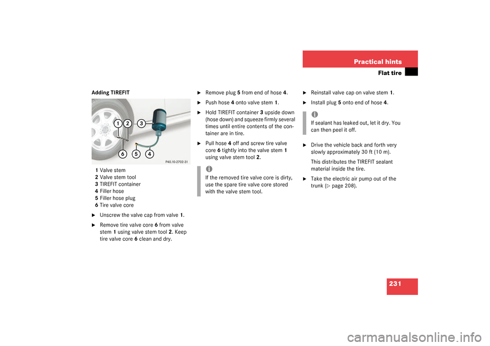
Adding TIREFIT
1Valve stem
2Valve stem tool
3TIREFIT container
4Filler hose
5Filler hose plug
6Tire valve core�
Unscrew the valve cap from valve1.
�
Remove tire valve core6 from valve
stem1 using valve stem tool2. Keep
tire valve core6 clean and dry.
�
Remove plug5 from end of hose4.
�
Push hose4 onto valve stem1.
�
Hold TIREFIT container3 upside down
(hose down) and squeeze firmly several
times until entire contents of the con-
tainer are in tire.
�
Pull hose4 off and screw tire valve
core6 tightly into the valve stem1
using valve stem tool2.
�
Reinstall valve cap on valve stem1.
�
Install plug5 onto end of hose4.
�
Drive the vehicle back and forth very
slowly approximately 30 ft (10 m).
This distributes the TIREFIT sealant
material inside the tire.
�
Take the electric air pump out of the
trunk (
�page 208).
iIf the removed tire valve core is dirty,
use the spare tire valve core stored
with the valve stem tool.
iIf sealant has leaked out, let it dry. You
can then peel it off.
Page 238 of 304
238 Practical hintsFlat tire�
Visit an authorized Mercedes-Benz
Center as soon as possible to obtain a
new TIREFIT kit.
�
Bring used TIREFIT materials to an au-
thorized Mercedes-Benz Center for
proper disposal.
�
Replace your TIREFIT container every
four years. Replacement containers are
available at your authorized
Mercedes-Benz Center.
Mounting the spare wheel
More information on spare wheels with
collapsible tires can be found in the “Tech-
nical data” section (
�page 265).Preparing the vehicle
Prepare the vehicle as described under
“Preparing the vehicle” on page
(
�page 229).
�
Turn pump holder counterclockwise to
loosen (
�page 207).
�
Take the spare wheel out of wheel well.
Lifting the vehicle
�
Prevent the vehicle from rolling away
by blocking wheels with wheel chocks
(not included) or other sizable objects.
When changing wheel on a level surface:
�
Place one chock in front of and one be-
hind the wheel that is diagonally oppo-
site to the wheel being changed.
When changing wheel on a hill:
�
Place chocks on the downhill side
blocking both wheels of the other axle.
�
Take the vehicle tool kit and the jack
out of the trunk.
Warning!
G
Do not exceed vehicle speed of 50 mph
(80 km/h). A TIREFIT repair is not designed
to operate at higher speeds.
The sticker must be attached on the instru-
ment cluster where it will be easily seen by
the driver.
Vehicle handling characteristics may
change. Adapt your driving accordingly.
Warning!
G
The dimensions of the spare wheel are dif-
ferent from those of the road wheels. As a
result, the vehicle handling characteristics
change when driving with a spare wheel
mounted. Adapt your driving style accord-
ingly.
The spare wheel is for temporary use only.
When driving with spare wheel mounted, en-
sure proper tire pressure and do not exceed
vehicle speed of 50 mph (80 km/h).
Drive to the nearest Mercedes-Benz Center
as soon as possible to have the spare wheel
replaced with a regular road wheel.
Never operate the vehicle with more than
one spare wheel mounted.
��
Page 241 of 304
241 Practical hints
Flat tire
�
Remove the wheel.
�
Take the spare tire out of the trunk.
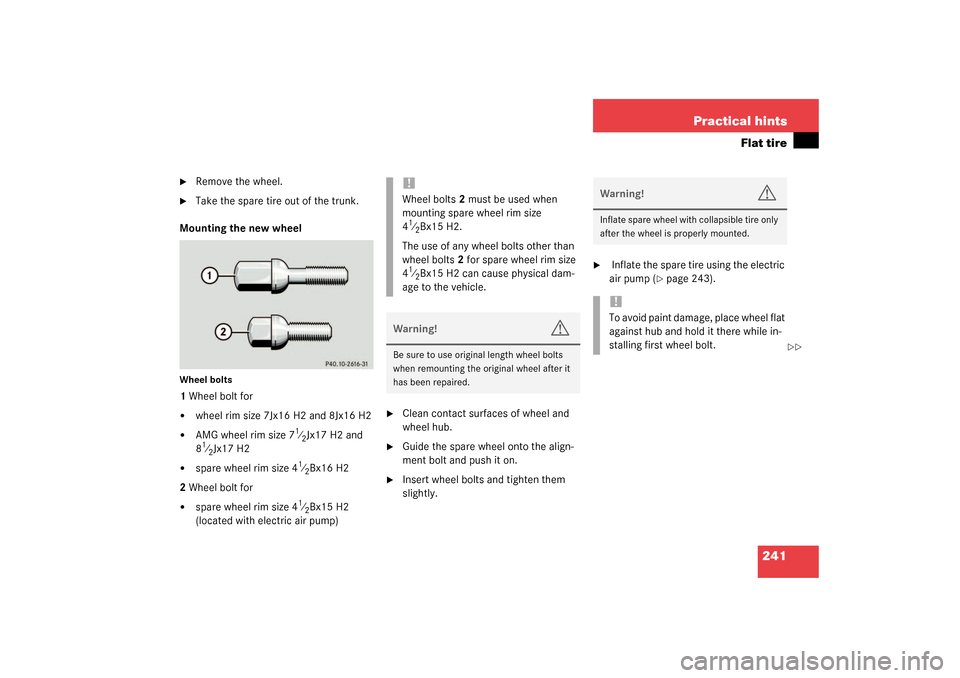
Mounting the new wheel
Wheel bolts1 Wheel bolt for�
wheel rim size 7Jx16 H2 and 8Jx16 H2
�
AMG wheel rim size 7
1⁄2Jx17 H2 and
8
1⁄2Jx17 H2
�
spare wheel rim size 4
1⁄2Bx16 H2
2 Wheel bolt for
�
spare wheel rim size 4
1⁄2Bx15 H2
(located with electric air pump)
�
Clean contact surfaces of wheel and
wheel hub.
�
Guide the spare wheel onto the align-
ment bolt and push it on.
�
Insert wheel bolts and tighten them
slightly.
�
Inflate the spare tire using the electric
air pump (
�page 243).
!Wheel bolts2 must be used when
mounting spare wheel rim size
41⁄2Bx15 H2.
The use of any wheel bolts other than
wheel bolts2 for spare wheel rim size
4
1⁄2Bx15 H2 can cause physical dam-
age to the vehicle.
Warning!
G
Be sure to use original length wheel bolts
when remounting the original wheel after it
has been repaired.
Warning!
G
Inflate spare wheel with collapsible tire only
after the wheel is properly mounted.!To avoid paint damage, place wheel flat
against hub and hold it there while in-
stalling first wheel bolt.
��
Page 243 of 304
243 Practical hints
Flat tire
�
Before storing the jack in the trunk, it
should be fully collapsed, with pin and
handle folded in.
Inflating the collapsible spare tire
�
Take the electric air pump out of the
trunk (
�page 207).
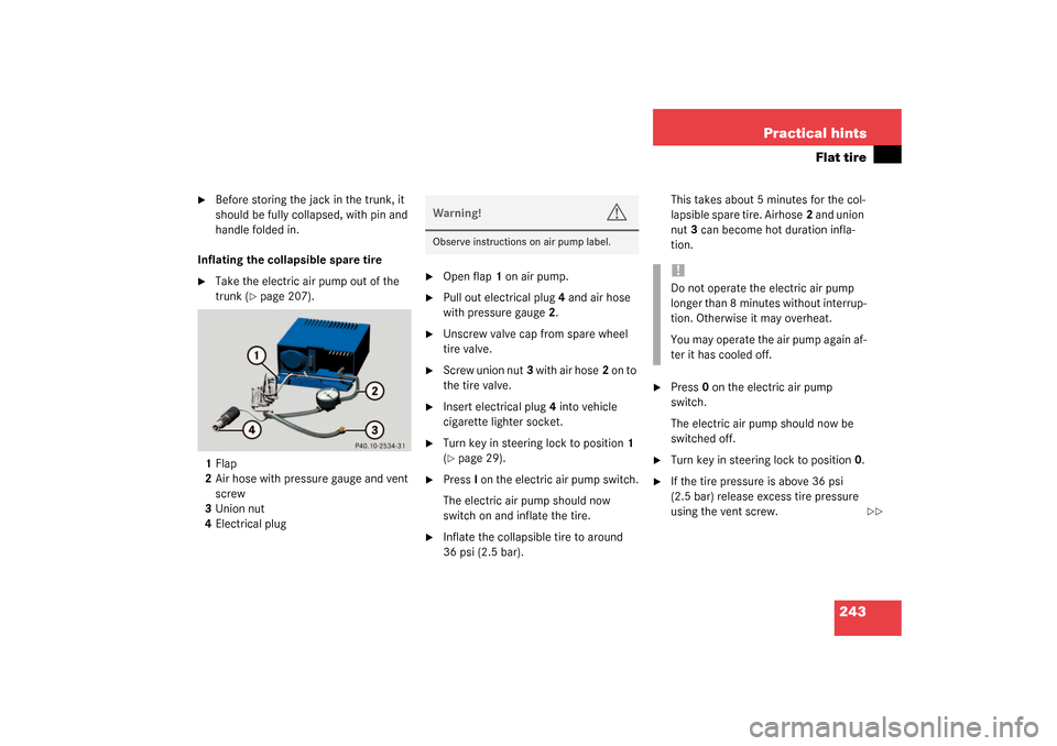
1Flap
2Air hose with pressure gauge and vent
screw
3Union nut
4Electrical plug
�
Open flap1 on air pump.
�
Pull out electrical plug4 and air hose
with pressure gauge2.
�
Unscrew valve cap from spare wheel
tire valve.
�
Screw union nut3 with air hose2 on to
the tire valve.
�
Insert electrical plug4 into vehicle
cigarette lighter socket.
�
Turn key in steering lock to position1
(�page 29).
�
PressI on the electric air pump switch.
The electric air pump should now
switch on and inflate the tire.
�
Inflate the collapsible tire to around
36 psi (2.5 bar).This takes about 5 minutes for the col-
lapsible spare tire. Airhose2 and union
nut3 can become hot duration infla-
tion.
�
Press0 on the electric air pump
switch.
The electric air pump should now be
switched off.
�
Turn key in steering lock to position0.
�
If the tire pressure is above 36 psi
(2.5 bar) release excess tire pressure
using the vent screw.
Warning!
G
Observe instructions on air pump label.
!Do not operate the electric air pump
longer than 8 minutes without interrup-
tion. Otherwise it may overheat.
You may operate the air pump again af-
ter it has cooled off.
��
Page 244 of 304
244 Practical hintsFlat tire
�
Detach the electric air pump.
�
Reinstall tire valve cap.
�
Stow the electrical plug and the air
hose behind the flap and place the air
pump back in the trunk.
�
Close the trunk lid.Storing collapsible spare wheel in
wheel well
Before you can store the spare wheel with
collapsible tire in the wheel well you have
to release the air pressure of the tire.
�
Unscrew valve stem removal tool,
which is part of the valve cap, from tire
valve.
�
Using the valve stem removal tool,
open tire valve slightly by turning the
tire valve insert counterclockwise to
release air pressure.
�
When the air pressure has been re-
leased, remove tire valve insert (pro-
tect it from dirt and sand) using the
previously removed tire valve cap.
�
Once all air is out of the tire, and the
tire has collapsed to its original shape,
reinstall the tire valve insert and valve
cap.
�
Place spare wheel in wheel well and
secure it with the pump holder.
�
Tu rn pu m p hold er cl ockwi se to its st op.
Warning!
G
Follow recommend inflation pressures.
Do not overinflate tires. Overinflating tires
can result in sudden deflation (blowout) be-
cause they are more likely to become punc-
tured or damaged by road debris, potholes
etc.
Do not underinflate tires. Underinflated tires
wear unevenly, adversely affect handling
and fuel economy, and are more likely to fail
from being overheated.
Do not overload the tires by exceeding the
specified vehicle capacity weight (as indicat-
ed by the label on the pillar in the driver’s
door opening). Overloading the tires can
overheat them, possibly causing a blowout.
Warning!
G
To prevent possible injury when unscrewing
air pump filler hose from tire valve after in-
flating the tire, use a rag since the tire valve
could be hot.
Page 255 of 304
255 Technical data
Spare parts service
Warranty coverage
Identification labels
Layout of poly-V-belt drive
Engine
Rims and Tires
Electrical system
Main Dimensions
Weights
Fuels, coolants, lubricants etc.
Consumer information
Page 265 of 304
265 Technical data
Rims and Tires
Spare wheel with collapsible tire
SLK 230 Kompressor
SLK 320
Rim (light alloy)
41⁄2Bx15 H2
41⁄2Bx16 H2
Wheel offset
0.47 in (12 mm)
0.47 in (12 mm)
Collapsible tire
165-15 89 P
1
165/70-16 92 P
1
1Must not be used with snow chains.i S L K 3 2 A M G h a s n o s p a r e w h e e l a n d i s
therefore equipped with TIREFIT.
Page 279 of 304
279 Technical terms
ABS
(A
ntilock B
rake S
ystem)
Prevents the wheels from locking up
during braking so that the vehicle can
continue to be steered.
Alignment bolt
Metal pin with thread. The centering
pin is an aid used when changing a tire
to align the wheel with the wheel hub.
BabySmart
TM
airbag deactivation
system
This system detects if a special system
compatible child restraint seat is in-
stalled on the passenger seat. The sys-
tem will automatically deactivate the
passenger front airbag when such a
seat is properly installed (indicator
lamp
7
in the center console lights
up). See your authorized
Mercedes-Benz Center for availability.BabySmart
TM
compatible child seats
Special restraint system for children.
The sensor system for the passenger
seat prevents deployment of the pas-
senger front airbag if a BabySmart
TM
compatible child seat is installed.
BAS
(B
rake A
ssist S
ystem)
System for potentially reducing braking
distances in emergency braking situa-
tions. The system is activated when it
senses an emergency based on how
fast the brake is applied.
CAC
(C
ustomer A
ssistance C
enter)
Mercedes-Benz customer service cen-
ter, which can help you with any ques-
tions about your vehicle and provide
assistance in the event of a break-
down.CAN system
(C
ontroller A
rea N
etwork)
Data bus network serving to control ve-
hicle functions such as door locking or
windshield wiping.
Cockpit
All instruments, switches, buttons and
indicator/warning lamps in the passen-
ger compartment needed for vehicle
operation and monitoring.
Collapsible tire
An especially compact spare tire that
must be inflated with a provided air
pump before using. It should only be
used to bring the vehicle to the nearest
service station.
Cruise control
Driving convenience system for auto-
matically maintaining the vehicle speed
set by the driver.