Page 166 of 376

166 Controls in detailRetractable hardtop2Close the fastening straps�
Guide the fastening straps around the
top of the roll bar and close the buck-
les.
�
Tighten the fastening straps if neces-
sary.
�
Lower the roll bar.
�
Fold the upper section of the wind
screen up towards the head restraints
until it stops.Removing
�
Fold the upper section of the wind
screen back down.
�
Raise the roll bar slightly (
�page 61).
1Release button
�
Undo the buckles on the upper section
of the roll bar by pressing the release
button1.
�
Lower the roll bar. Make sure that the
fastening straps do not get caught.
�
Pull the wind screen out towards the
front of the vehicle. Be careful not to
damage interior trim with the guide
tabs.
�
Place the wind screen back into the
bag.
Sunshade for panorama roof*
The sunshade protects you from excessive
sunlight coming in through the panorama
roof.Warning!
G
Do not operate the sunshade while driving.
Adjusting the sunshade while driving could
cause the driver to lose control of the vehi-
cle.
Page 167 of 376
167 Controls in detail
Retractable hardtop
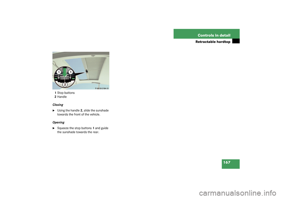
1Stop buttons
2Handle
Closing�
Using the handle2, slide the sunshade
towards the front of the vehicle.
Opening
�
Squeeze the stop buttons1 and guide
the sunshade towards the rear.
Page 179 of 376
179 Controls in detail
Driving systems
1Distance warning function on/off
switch
2Thumbwheel for setting distance
Increasing distance
Increasing the distance setting tells Dis-
tronic to maintain a greater following dis-
tance to the vehicle ahead.�
Turn thumbwheel2 towards
¯
.Decreasing distance
Decreasing the distance setting tells Dis-
tronic to maintain a smaller following dis-
tance to the vehicle ahead.
�
Turn thumbwheel2 towards
®
.Distance warning function
When Distronic is deactivated, this func-
tion will continue to warn you if you are fol-
lowing too close to the vehicle ahead:
�
The DTR warning lamp
E
lights up
red.
�
An intermittent warning will sound if
necessary.
If these warnings are issued, you must
brake manually to maintain a safe distance
and avoid a collision with the vehicle
ahead.
Page 190 of 376
190 Controls in detailUseful features
Useful featuresInterior storage spaces Glove box
An AUX socket to the audio system for por-
table audio devices is installed in the glove
box.
1Button to open
2Glove box
Opening the glove box
�
Press button1.
The glove box lid opens downward.
Closing the glove box
�
Push lid up to close.Cup holders
1Left cup holder
2Right cup holder
Opening
�
Briefly press cup holder cover.
The cup holder opens automatically.
Warning!
G
To help avoid personal injury during a colli-
sion or sudden maneuver, exercise care
when stowing objects in the vehicle. Put lug-
g a g e o r c a r g o i n t h e t r u n k i f p o s s i b l e . D o n o t
pile luggage or cargo higher than the seat
backs. Do not place anything on shelf be-
hind roll bar.
Parcel nets cannot secure hard or heavy ob-
jects. Warning!
G
Keep compartment lids closed. This will help
to prevent stored objects from being thrown
about and injuring vehicle occupants during
an accident.
Page 195 of 376
195 Controls in detail
Useful features
Parcel net in trunk
There are three nets available in the trunk
to secure loads:�
a pocket net on each side of the right
and left trunk side walls
�
a trunk floor net
�
Pull the trunk floor net from the trunk
back wall towards the front over the
luggage.
�
Hang the hooks of the net on the eyes
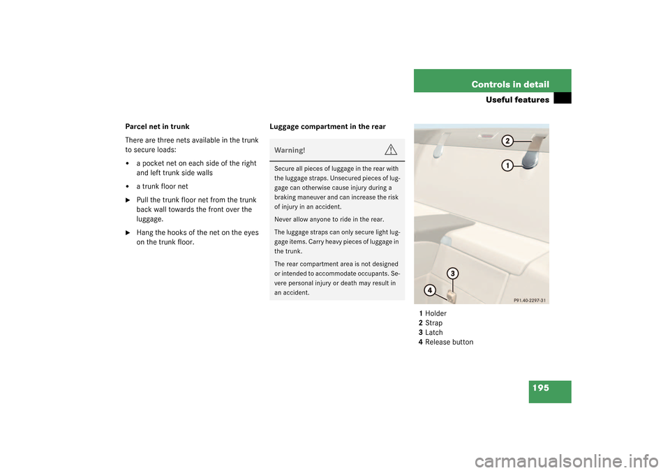
on the trunk floor.Luggage compartment in the rear
1Holder
2Strap
3Latch
4Release button
Warning!
G
Secure all pieces of luggage in the rear with
the luggage straps. Unsecured pieces of lug-
gage can otherwise cause injury during a
braking maneuver and can increase the risk
of injury in an accident.
Never allow anyone to ride in the rear.
The luggage straps can only secure light lug-
gage items. Carry heavy pieces of luggage in
the trunk.
The rear compartment area is not designed
or intended to accommodate occupants. Se-
vere personal injury or death may result in
an accident.
Page 202 of 376

or airbags deploy,
�
if")
202 Controls in detailUseful features
Emergency calls
An emergency call is initiated automatical-
ly:�
following an accident in which the
emergency tensioning devices (ETDs)
or airbags deploy,
�
if the anti-theft alarm or the tow-away
alarm stays on for more than
20 seconds. See anti-theft alarm sys-
tem (
�page 75) and tow-away alarm
(
�page 77).
An emergency call can also be initiated
manually by opening the cover next to the
inside rear view mirror labeled SOS, then
briefly pressing the button located under
the cover. See below for instructions on
initiating an emergency call manually.Once the emergency call is in progress, the
indicator lamp in the SOS button will begin
to flash. The message
Emergency call –
Connecting call
appears in the multifunc-
tion display. When the connection is estab-
lished, the message
Emergency call –
Call connected
appears in the multifunc-
tion display. All information relevant to the
emergency, such as the location of the ve-
hicle (determined by the GPS satellite loca-
tion system), vehicle model, identification
number and color are generated.
A voice connection between the Response
Center and the occupants of the vehicle
will be established automatically soon af-
ter the emergency call has been initiated.
When a voice connection is established the
audio system mutes and the message
Tele Aid
Emergency call active
appears
in the multifunction display. The Response
Center will attempt to determine more pre-
cisely the nature of the accident provided
they can speak to an occupant of the vehi-
cle.
Warning!
G
If the indicator lamps in the SOS button, in
the Roadside Assistance button, and/or in
the Information button do not come on dur-
ing the system self-check, or if any of these
indicators remain illuminated continuously
in red and/or the message
TELE AID -
VISIT WORKSHOP!
is displayed in the mul-
tifunction display after the system
self-check, a malfunction in the system has
been detected.
If a malfunction is indicated as outlined
above, the system may not operate as ex-
pected. Have the system checked at the
nearest Mercedes-Benz Center as soon as
possible
Page 204 of 376

204 Controls in detailUseful features
Roadside Assistance button
•
Located below the center armrest cover is
the Roadside Assistance button
•
.
�
Press and hold the button (for longer
than 2 seconds)
A call to a Mercedes-Benz Roadside As-
sistance dispatcher will be initiated.
The button will flash while the call is in
progress. The message
Roadside as-
sistance – Connecting call
will ap-
pear in the multifunction display.
When the connection is established, the
message
Roadside assistance –
Call connected
appears in the multifunc-
tion display. The Tele Aid system will trans-
mit data generating the vehicle
identification number, model, color and lo-
cation (subject to availability of cellular
and GPS signals).A voice connection between the Roadside
Assistance dispatcher and the occupants
of the vehicle will be established. When a
voice connection is established the audio
system mutes and the message
Tele Aid
Roadside assistance call active
ap-
pears in the multifunction display.
�
Describe the nature of the need for as-
sistance.
The Mercedes-Benz Roadside assistance
dispatcher will either dispatch a qualified
Mercedes-Benz technician or arrange to
tow your vehicle to the nearest
Mercedes-Benz Center. For services such
as labor and / or towing, charges may ap-
ply. Refer to the Roadside Assistance man-
ual for more information.
Warning!
G
If you feel at any way in jeopardy when in the
vehicle (e.g. smoke or fire in the vehicle, ve-
hicle in a dangerous road location), please
do not wait for voice contact after you have
pressed the emergency button. Carefully
leave the vehicle and move to a safe loca-
tion. The Response Center will automatically
contact local emergency officials with the
vehicle’s approximate location if they re-
ceive an automatic SOS signal and cannot
make voice contact with the vehicle occu-
pants.
Page 216 of 376

216 OperationDriving instructionsPower assistance
Brakes
Warning!
G
The brake system requires electrical energy
for operation.
A malfunction in the vehicle’s power supply
or electrical system In such a case, the red
brake warning lamp (
�page 253) and warn-
ing messages (
�page 265) in the instru-
ment cluster light up while driving. To brake,
the driver must then apply significantly
greater brake pedal pressure and depress
the pedal much further to obtain the expect-
ed braking effect. If necessary, apply full
pressure to the brake pedal. Brakes are only
applied to the front wheels. Stopping dis-
tance is increased! If there is a malfunction
in the SBC brake system, we recommend
that the vehicle be transported with all
wheels off the ground using flatbed or ap-
propriate wheel lift/dolly equipment.
A tow bar must be used if circumstances do
not permit the use of the recommended
towing methods and the vehicle requires
towing with all four wheels on the ground.
Towing the vehicle with all four wheels on
the ground is only permissible for distances
up to 30 miles (50 km) and at a speed not to
exceed 30 mph (50 km/h). For more infor-
mation, refer to "Towing the vehicle"
(�page 325).
With the engine not running, there is no
power assistance for the steering system. In
this case, it is important to keep in mind that
a considerably higher degree of effort is nec-
essary to steer the vehicle.
Warning!
G
After driving in heavy rain for some time
without applying the brakes or through wa-
ter deep enough to wet brake components,
the first braking action may be somewhat
reduced and increased pedal pressure may
be necessary to obtain expected braking ef-
fect. Maintain a safe distance from vehicles
in front.
Resting your foot on the brake pedal will
cause excessive and premature wear of the
brake pads.
It can also result in the brakes overheating
thereby significantly reducing their effec-
tiveness. It may not be possible to stop the
vehicle in sufficient time to avoid an acci-
dent.