Page 34 of 376

34 Getting startedAdjustingHead restraint tilt�
Manually adjust the angle of the head
restraint. Push or pull on the lower
edge of the head restraint cushion.
More information can be found in the
“Controls in detail” section (
�page 93).
Steering wheelThe stalk is located on the steering column
(lower left).
�
Make sure that the ignition is switched
on.
All the lights in the instrument cluster
light up.
1Steering column, lengthen or shorten
2Steering column, height
Steering column, lengthen or shorten
�
Move stalk forward or back in the direc-
tion of arrow1 until a comfortable
steering wheel position is reached with
your arms slightly bent at the elbow.
iThe memory function (
�page 99) lets
you store the steering wheel adjust-
ment together with the adjustment for
the seat and the exterior rear view mir-
rors.
Warning!
G
Do not adjust the steering wheel while driv-
ing. Adjusting the steering wheel while driv-
ing could cause the driver to lose control of
the vehicle.
When leaving the vehicle, always remove the
key from the starter switch, and take the
KEYLESS-GO
* card (if so equipped) with
you.
The steering wheel adjustment feature can
also be operated with the driver’s door
open. Do not leave children unattended in
the vehicle, or with access to an unlocked
vehicle. Unsupervised use of vehicle equip-
ment may cause an accident and/or serious
personal injury.
Page 36 of 376

36 Getting startedAdjusting
�
Make sure that the ignition is switched
on.
All the lights in the instrument cluster
light up.
�
Press button1 for the left mirror or
button2 for the right mirror.
�
Push adjustment button3 up, down,
left or right according to the setting de-
sired.More information can be found in the
“Controls in detail” section (
�page 145).
Warning!
G
Exercise care when using the passenger
side exterior rear view mirror. The mirror
surface is convex (outwardly curved surface
for a wider field of view). Objects in mirror
are closer than they appear. Check your in-
side rear view mirror or glance over your
shoulder before changing lanes. Warning!
G
In case of an accident, liquid electrolyte may
escape the mirror housing if the mirror glass
breaks.
Electrolyte has an irritating effect. Do not al-
low the liquid to come into contact with
eyes, skin, clothing, or respiratory system.
In case it does, immediately flush the affect-
ed area with water, and seek medical help if
necessary.
!Electrolyte drops coming into contact
with the vehicle paint finish can only be
completely removed while in their liq-
uid state and by applying plenty of wa-
ter.iThe memory function (
�page 99) lets
you store the steering wheel adjust-
ment together with the adjustment for
the seat and the exterior rear view mir-
rors.
!If an exterior rear view mirror housing
is forcibly pushed forward or rearward,
reposition it by applying firm pressure
until it snaps into place. The mirror
housing is now properly positioned and
you can adjust the mirror normally.
Page 52 of 376

52 Safety and SecurityOccupant safety
Occupant safetyIn this section you will learn the most im-
portant facts about the restraint systems
of the vehicle.
The restraint systems are�
Seat belts
�
Emergency tensioning device
�
Airbags
�
Child seats
�
Child seat recognition
As independent systems their protective
effects work in conjunction with each oth-
er.The
1
warning lamp in the instrument
cluster lights up for about 4 seconds when
you turn the key in the starter switch to po-
sition 1 or 2, or press the KEYLESS-GO* (if
so equipped) start/stop button once or
twice. It goes out when you start the en-
gine. This shows that the restraint systems
are operational.
If the lamp does not come on at all or if it
fails to extinguish after approximately 4
seconds or if it comes on thereafter, a mal-
function in the system has been detected.
More information can be found in the
"Practical hints" section (
�page 252).
iFor information on infants and children
traveling with you in the vehicle and re-
straint systems for infants and chil-
dren, see “Children in the vehicle”
(�page 62).
Warning!
G
In the event that the SRS malfunction indica-
tor lamp lights up during driving or does not
come on at all, the SRS may not be opera-
tional. For your safety, we strongly recom-
mend that you visit an authorized
Mercedes-Benz Center immediately to have
the system checked; otherwise the SRS may
not be activated when needed in an acci-
dent, which could result in serious or fatal
injury, or it might deploy unexpectedly and
unnecessarily which could also result in inju-
ry.
Improper work on the restraint systems can
lead to unintentional deployment or opera-
tional failure.
In addition, through improper work there is
a risk of rendering the SRS inoperative or
causing unintended airbag deployment.
Work on the SRS must therefore only be per-
formed by an authorized Mercedes-Benz
Center.
Page 79 of 376
79 Controls in detail
Locking and unlocking
Seats
Memory function
Lighting
Instrument cluster
Control system
Automatic transmission
Good visibility
Automatic climate control
Power windows
Retractable hardtop
Driving systems
Useful features
Page 93 of 376
93 Controls in detail
Seats
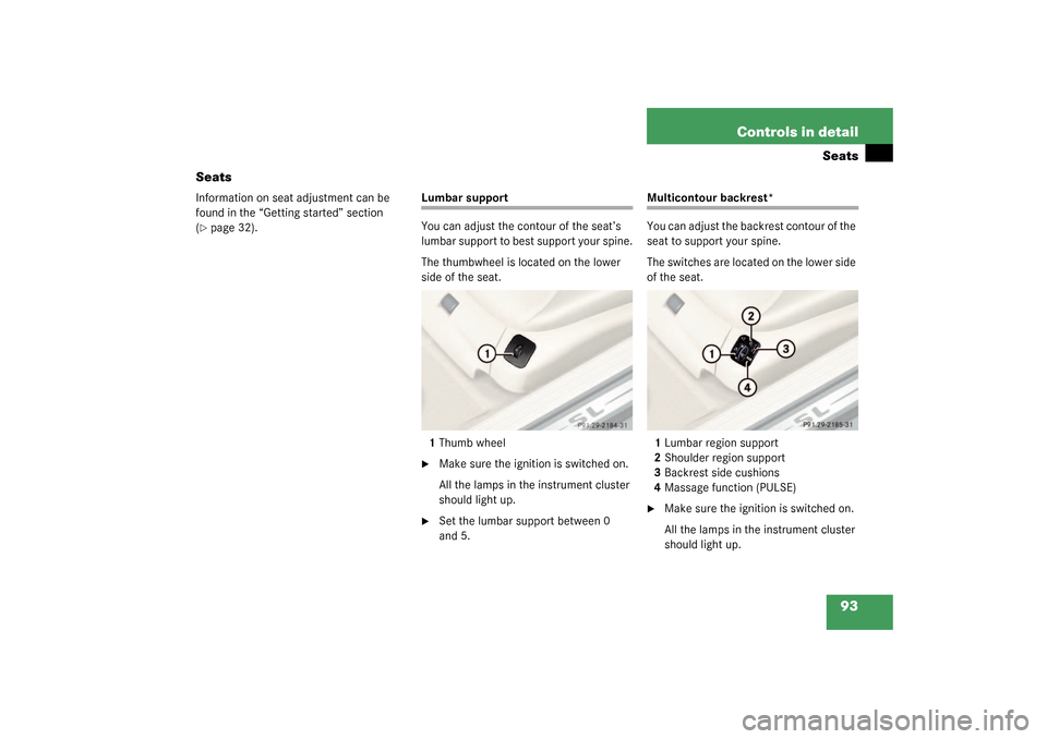
Seats
Information on seat adjustment can be
found in the “Getting started” section
(�page 32).
Lumbar support
You can adjust the contour of the seat’s
lumbar support to best support your spine.
The thumbwheel is located on the lower
side of the seat.
1Thumb wheel�
Make sure the ignition is switched on.
All the lamps in the instrument cluster
should light up.
�
Set the lumbar support between 0
and 5.
Multicontour backrest*
You can adjust the backrest contour of the
seat to support your spine.
The switches are located on the lower side
of the seat.
1Lumbar region support
2Shoulder region support
3Backrest side cushions
4Massage function (PULSE)�
Make sure the ignition is switched on.
All the lamps in the instrument cluster
should light up.
Page 96 of 376

96 Controls in detailSeatsSeat ventilation*
The switch is located on the door. The blue
indicator lamps on the switch show the
ventilation level selected:
1Seat ventilation switch�
Make sure the ignition is switched on.All the lamps in the instrument cluster
light up.
Switching on the seat ventilation
�
Press switch1.
Three blue indicator lamps on the
switch light up.
Switching off the seat ventilation
�
Press switch1 repeatedly until all indi-
cator lamps go out.
Level 3
Three indicator lamps on
Level 2
Two indicator lamps on
Level 1
One indicator lamp on
Ventilation off
No indicator lamp on
iIn normal operation the seat ventilation
will switch off automatically after about
30 minutes.
!If one or all of the lamps blink on the
seat ventilation* switch, there is insuf-
ficient voltage since too many electri-
cal consumers are switched on. The
seat ventilation* switches off automat-
ically.
The seat ventilation* will switch back
on again automatically as soon as suffi-
cient voltage is available.
Page 97 of 376

97 Controls in detail
Seats
Seat heater
Vehicles without seat ventilation*
The switch is located on the door.
1Normal heating
2Rapid heating�
Make sure the ignition is switched on.
All the lamps in the instrument cluster
light up.Switching on the seat heater
�
Press lower switch position1.
A red indicator lamp on the switch
lights up.
Switching off the seat heater
�
Press lower switch position1 again.
Rapid seat heating mode
�
Press upper switch position2.
Both red indicator lamps on the switch
light up. Switching off rapid seat heating mode
�
Press upper switch position2 again.
iThe seat heater will be automatically
switched off after approximately
30 minutes. iThe system switches over to normal
heating mode after approximately five
minutes. Only the right-hand indicator
lamp remains lit.
!If one or both of the lamps on the seat
heater switch are blinking, there is in-
sufficient voltage available since too
many electrical consumers are turned
on. The seat heater switches off auto-
matically.
The seat heater will switch back on
again automatically as soon as suffi-
cient voltage is available.
Page 98 of 376

98 Controls in detailSeatsVehicles with seat ventilation*
The switch is located on the door. The red
indicator lamps on the switch show the
heater level selected:
1Seat heater switch�
Make sure the ignition is switched on.
All the lamps in the instrument cluster
light up.Switching on the seat heater
�
Press upper switch position1 twice.
A red indicator lamp on the switch
lights up.
Switching off the seat heater
�
Press upper switch position1 again.
Rapid seat heating
�
Press upper switch position1 once.
Both indicator lamps on the switch light
up. Switching off rapid seat heating mode
�
Press upper switch position1 twice.
Seat heater off
No indicator lamp on
Level 1
One indicator lamp on
Level 2
Two indicator lamps on
iThe seat heater will be automatically
switched off after approximately
30 minutes. iThe system switches over to normal
heating mode after approximately five
minutes. Only the right-hand indicator
lamp remains lit.
!If one or both of the lamps on the seat
heater switch are blinking, there is in-
sufficient voltage available since too
many electrical consumers are turned
on. The seat heater switches off auto-
matically.
The seat heater will switch back on
again automatically as soon as suffi-
cient voltage is available.