Page 107 of 376
107 Controls in detail
Lighting
Manual control
Switching lamps on�
Press switch3.
The interior lighting switches on.
Switching lamps off
�
Press switch3 again.
The interior lighting switches off.
Courtesy lighting
For better orientation in the dark, courtesy
lamps will illuminate the interior of your ve-
hicle as follows:
With parking lamps switched on:�
the door handles
�
the driver and passenger footwells
With key in starter switch position1:
�
the door handles
�
the center console
iThe setting selected for the interior
lighting is used for the trunk lighting as
well.
If you leave the trunk lid open for an ex-
tended period of time, the trunk light-
ing will switch off automatically after
approximately ten minutes.
iIf you turn the key in the starter switch
to position0 and switch off the exterior
headlamps, the door handle lamps will
remain lit for approximately five min-
utes.
Page 195 of 376
195 Controls in detail
Useful features
Parcel net in trunk
There are three nets available in the trunk
to secure loads:�
a pocket net on each side of the right
and left trunk side walls
�
a trunk floor net
�
Pull the trunk floor net from the trunk
back wall towards the front over the
luggage.
�
Hang the hooks of the net on the eyes
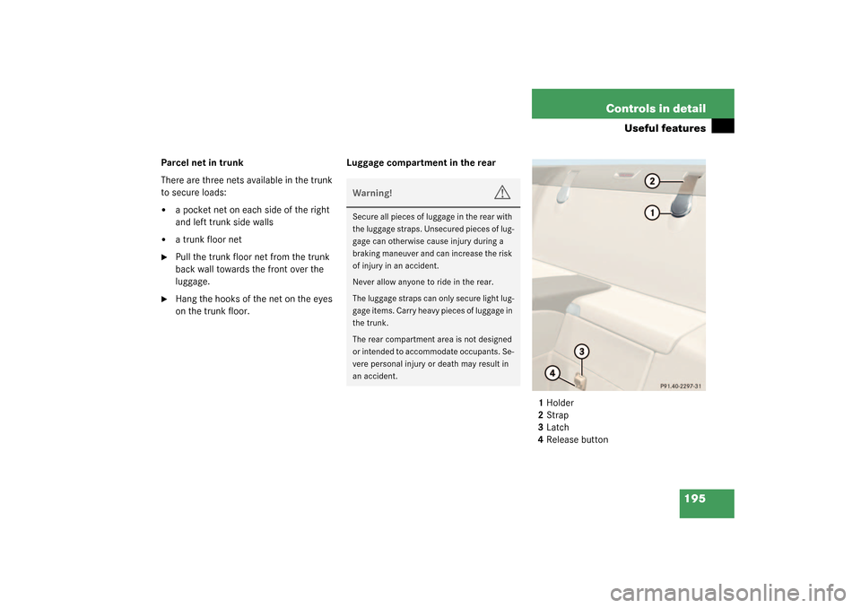
on the trunk floor.Luggage compartment in the rear
1Holder
2Strap
3Latch
4Release button
Warning!
G
Secure all pieces of luggage in the rear with
the luggage straps. Unsecured pieces of lug-
gage can otherwise cause injury during a
braking maneuver and can increase the risk
of injury in an accident.
Never allow anyone to ride in the rear.
The luggage straps can only secure light lug-
gage items. Carry heavy pieces of luggage in
the trunk.
The rear compartment area is not designed
or intended to accommodate occupants. Se-
vere personal injury or death may result in
an accident.
Page 198 of 376

198 Controls in detailUseful featuresSwitching on�
Make sure that the ignition is switched
on.
All the lamps in the instrument cluster
should light up.
�
Turn lever in the direction of arrow1.
The steering wheel is heated. Indicator
lamp2 lights up.
Switching off
�
Turn lever in the direction of arrow3.
The steering wheel heating is turned
off. Indicator lamp2 goes out.
Easy-Pack load assist in the trunk
To facilitate trunk loading after opening the
lid, use the Easy-Pack feature to raise the
retracted hardtop from its storage position
in the trunk.
1Retracted hardtop
2Luggage cover
3Easy-Pack buttonRaising the hardtop
The hardtop can only be raised when the
luggage cover is closed and the trunk lid is
completely opened.
�
Press button3.
The hardtop rises a short distance.
Button3 lights up brightly. You can
now open the luggage cover.
iThe steering wheel heating does not
turn off automatically.
Warning!
G
To prevent injuries, make sure that there is
no possibility of body parts getting caught in
moving parts. If potential danger exists,
press the switch again. This will immediately
stop the movement of the hardtop.
Page 199 of 376

199 Controls in detail
Useful features
Lowering the hardtop
The hardtop can only be lowered when the
luggage cover is closed and the trunk lid is
completely opened.�
Close the luggage cover.
�
Press button3.
The hardtop lowers. Button3 is dimly
lit.
Electrical outlet
An electrical outlet is located on the right
side of the trunk.�
Turn the key in the starter switch to
position1 or2.
�
Flip up cover and insert electrical plug
(cigar lighter type).
Telephone*
Radio transmitters, such as a portable tele-
phone or a citizens band unit, should only
be used inside the vehicle if they are con-
nected to an antenna that is installed on
the outside of the vehicle.
The external antenna must be approved by
Mercedes-Benz. Please contact an autho-
rized Mercedes-Benz Center for informa-
tion on the installation of an approved
external antenna. Refer to the radio trans-
mitter operation instructions regarding use
of an external antenna.
!Only close the trunk if the roof is com-
pletely lowered. Otherwise you could
damage the hardtop.
If you begin to close the trunk lid before
the hardtop is completely lowered, the
button3 will blink and a warning will
sound.
iThe electrical outlet can be used to ac-
commodate electrical consumers (e.g.
air pump, auxiliary lamps) up to a max-
imum of 180 W.
Warning!
G
Never operate radio transmitters equipped
with a built-in or attached antenna (i.e. with-
out being connected to an external antenna)
from inside the vehicle while the engine is
running. Doing so could lead to a malfunc-
tion of the vehicle’s electronic system, pos-
sibly resulting in an accident and/or serious
personal injury.
Page 299 of 376

299 Practical hints
Replacing bulbs
�
Turn the locking mechanism 2 clock-
wise.
�
Plug the connector onto the bulb.
�
Align headlamp cover and click into
place.
Replacing parking and standing lamp
bulbs
�
Switch off the lights.
�
Open the hood (
�page 227).
�
Press ends of headlamp cover tab to-
gether and remove cover.
�
Pull out the bulb socket with the bulb.
�
Pull the bulb out of the bulb socket.
�
Insert a new bulb in the socket.
�
Reinstall the bulb socket.
�
Align headlamp cover and click into
place.Replacing side marker lamp
�
Switch off the lights.
�
Carefully slide lamp towards rear.
�
Remove front end first.
�
Twist bulb socket counterclockwise
and pull out.
�
Pull bulb out of the bulb socket.
�
Insert new bulb in socket.
�
Reinstall bulb socket, push in, and twist
clockwise.
�
To reinstall lamp, set rear end in
bumper and let front end snap into
place.
Replacing bulbs for rear lamps
Tail lamp assemblies
1Backup lamp
2Turn signal lamp
3Driver’s side: Rear fog lamp
Passenger’s side: Substitute lamp�
Switch off the lights.
�
Open the trunk lid (
�page 83).
�
Fold trim to side and remove.
�
Twist bulb socket counterclockwise
and pull out.
iHave the headlamp adjustment
checked regularly.
��
Page 305 of 376
.
This distributes the TIREFIT sealant ma-
terial inside the tire.
�
Take the electric air pump")
305 Practical hints
Flat tire
�
Drive the vehicle back and forth very
slowly approximately 30 ft (10 m).
This distributes the TIREFIT sealant ma-
terial inside the tire.
�
Take the electric air pump out of the
trunk.
1Flap
2Air hose with pressure gauge and vent
screw
3Union nut
4Electrical plug
�
Open flap 1 on air pump.
�
Pull out electrical plug 4 and air hose
with the pressure gauge 2.
�
Screw the air hose 2 onto the tire valve.
�
Insert electrical plug 4 into vehicle ci-
gar lighter socket.
�
Turn the key in the ignition to position
1 (
�page 29).
or
�
Press the KEYLESS-GO* start/stop
button on the selector lever once. Do
not depress brake pedal.
�
Press I on the electric air pump switch.
The electric air pump should now
switch on and inflate the tire.
After 5 minutes, the pressure gauge must
display at least 26 psi (1.8 bar). The air
hose and the union nut can become hot
during inflation. Please exercise appropri-
ate caution.
�
If this tire pressure is not attained, turn
off the electric air pump, detach the air
hose from the tire valve, and again
drive vehicle back and forth very slowly
approximately 30 ft (10 m).
This serves to better distribute the
TIREFIT sealant material inside the tire.
�
Inflate the tire again.
Warning!
G
Observe safety instructions on air pump la-
bel.
Page 316 of 376
.
1Flap
2Air hose with pressure gauge and vent
screw
3Union nut
4Electrical plug
�
Open")
316 Practical hintsFlat tireInflating the spare tire�
Take the electric air pump out of the
trunk (
�page 289).
1Flap
2Air hose with pressure gauge and vent
screw
3Union nut
4Electrical plug
�
Open flap 1 on air pump.
�
Pull out the electrical plug 4 and air
hose with the pressure gauge 2.
�
Remove the valve cap from the tire
valve.
�
Screw the air hose 2 onto the tire valve.
�
Insert electrical plug 4 into vehicle ci-
gar lighter socket.
�
Turn the key in the ignition to
position1.
or
�
Press the KEYLESS-GO* start/stop
button on the selector lever once with-
out depressing the brake pedal.
�
Press 1 on the electric air pump switch.
The electric air pump should now
switch on and inflate the tire.
�
Inflate the tire to approx. 36 psi
(2.5 bar).
This takes about five minutes for the
spare tire. The air hose 2 and the union
nut 3 can become hot duration infla-
tion. Exercise proper caution to avoid
burning yourself when using the equip-
ment.
!Do not lower the vehicle before inflat-
ing the spare wheel tire. Otherwise the
rim may be damaged.Warning!
G
Observe instructions on air pump label.
Page 359 of 376

359 Index
Brakes 216
Warning lamp 253
Break-in period 214
Bulbs, replacing
Backup lamps 299
Brake lamps 296
Front lamps 295, 298
License plate lamps 300
Parking lamps 299
Rear fog lamp 299
Standing lamps 299
Tail lamp assemblies 299
Turn signal lamps, front 298
Turn signal lamps, rear 299
C
CAC (Customer Assistance Center) 351
CAN System 351
Capacities
Fuels, coolants, lubricants etc. 342
Catalytic converter 223
CD player
Operating 116
Center air vents 23
Center console
Lower part 24
Upper part 23Centigrade
Setting temperature units 122
Central locking
Automatic 91
Central locking switch 92
Switching on/off (control
system) 128
Unlocking from inside 92
Central locking switch 23
Central unlocking switch 23
Changing
Batteries (key) 293
Batteries (KEYLESS-GO* card) 294
Key setting 81
KEYLESS-GO* card setting 86
Vehicle level 185
Charging
Vehicle batteries 321
CHECK ENGINE malfunction indicator
lamp 21, 256
Checking
Batteries (KEYLESS-GO* card) 87
Coolant level 230
Oil level 226, 228
Tire inflate pressure 226
Vehicle lighting 226Vehicle lock status (KEYLESS-GO*
card) 87
Child safety
Airbags 54
Automatic child seat recognition 64
Infant and child restraint systems 52
Cigarette lighter 23, 197
Cleaning
Headlamps 146
Windshield 44
Clock 19
Closing
Glove box 190
Hood 228
Retractable hardtop (electronic
key) 164
Retractable hardtop (switch) 161
Side windows 158
Side windows (KEYLESS-GO*) 88
Sunshade* 167
Trunk lid 83, 91
Cockpit 352
Collapsible tire 352
COMAND 23
COMAND* 352
COMAND*, radio and telephone 222