Page 328 of 416

328 Practical hintsUnlocking/locking in an emergencyChanging batteries
If the batteries in the SmartKey or the
KEYLESS-GO* card are discharged, the ve-
hicle can no longer be locked or unlocked.
It is recommended to have the batteries re-
placed at an authorized Mercedes-Benz
Center.Batteries contain materials that can harm
the environment if disposed of improperly.
Recycling of batteries is the preferred
method of disposal. Many states require
sellers of batteries to accept old batteries
for recycling.SmartKey
1Mechanical key
2Battery compartment
Replacement batteries: Lithium, type
CR 2025 or equivalent.
�
Remove mechanical key1.
�
Insert the mechanical key in side open-
ing and push gray slide.
The battery compartment is unlatched.
�
Pull the battery compartment out of the
SmartKey housing in direction of ar-
row.
�
Remove the batteries.
Warning!
G
Keep the batteries out of reach of children.
If a battery is swallowed, seek medical help
immediately.
iWhen changing batteries, always re-
place both batteries.
The required replacement batteries are
available at any authorized
Mercedes-Benz Center.
Page 332 of 416

332 Practical hintsReplacing bulbsRear lamps Notes on bulb replacement
�
Use only 12 volt bulbs of the same type
and with the specified watt rating.
�
Switch lights off before changing a bulb
to prevent short circuits.
�
Always use a clean lint-free cloth when
handling bulbs.
�
Your hands should be dry and free of oil
and grease.
�
If the newly installed bulb does not light
up, visit an authorized Mercedes-Benz
Center.
�
Have the LEDs and bulbs for the follow-
ing lamps replaced by an authorized
Mercedes-Benz Center.�
Additional turn signal lamps in the
exterior rear view mirrors
�
High mounted brake lamp
�
Bi-Xenon lamps*
�
Front fog lamps
Lamp
Type
8
Brake lamp
LED
9
Turn signal lamp
PY 21 W
10
Tail and standing
lamp, side marker
P21/4W
11
Backup lamp
P21W
12
License plate lamps
C5W
13
Tail lamp, Rear fog
lamp
P21/4W
14
High mounted brake
lamp
LED
Warning!
G
Keep bulbs out of reach of children.
Bulbs and bulb sockets can be very hot. Al-
low the lamp to cool down before changing
a bulb.
Halogen lamps contain pressurized gas. A
bulb can explode if you:�
touch or move it when hot
�
drop the bulb
�
scratch the bulb
Wear eye and hand protection.
Because of high voltage in Bi-Xenon lamps,
it is dangerous to replace the bulb or repair
the lamp and its components. We recom-
mend that you have such work done by a
qualified technician.
Page 333 of 416
333 Practical hints
Replacing bulbs
Replacing bulbs for front lamps
1Headlamp cover for fog lamp
2Headlamp cover for high beam head-
lamp bulb, parking and standing lamp
3Headlamp cover for low beam
(Bi-Xenon* or halogen) headlamp bulb4Bulb socket for fog lamp
5Bulb socket for parking and standing
lamp
6Electrical connector for high beam
headlamp bulb
7Electrical connector for low beam
headlamp bulb
8Bulb socket for turn signal lampReplacing low beam bulbs
Bi-Xenon* headlamp
Halogen headlamp
�
Switch off the lights.
�
Open the hood (
�page 263).
�
Press the tab on cover3 and remove
cover.
�
Pull connector7 off of the lamp.
�
Release the retaining springs and take
out the bulb.Warning!
G
Do not remove the cover for the Bi-Xenon
headlamp. Because of high voltage in xenon
lamps, it is dangerous to replace the bulb or
repair the lamp and its components. We rec-
ommend that you have such work done by a
qualified technician.
��
Page 337 of 416
337 Practical hints
Replacing wiper blades
Replacing wiper blades
Removing�
Turn SmartKey in starter switch
position1.
�
Turn combination switch to wiper
settingII (
�page 47).
�
With wiper arm in vertical position (see
above), turn SmartKey in starter switch
to position0.
�
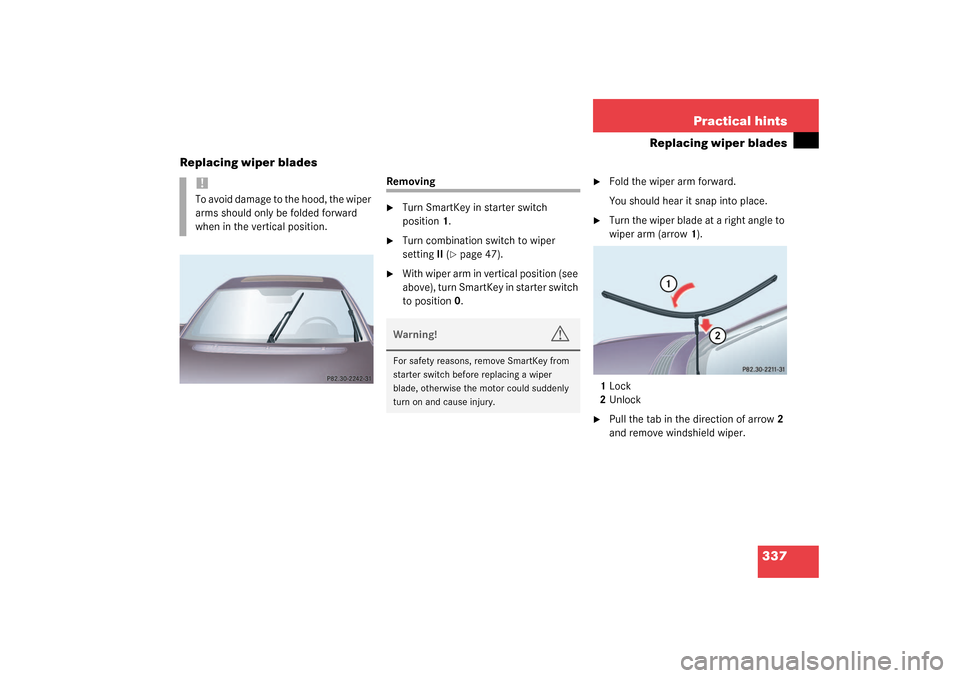
Fold the wiper arm forward.
You should hear it snap into place.
�
Turn the wiper blade at a right angle to
wiper arm (arrow 1).
1Lock
2Unlock
�
Pull the tab in the direction of arrow2
and remove windshield wiper.
!To avoid damage to the hood, the wiper
arms should only be folded forward
when in the vertical position.
Warning!
G
For safety reasons, remove SmartKey from
starter switch before replacing a wiper
blade, otherwise the motor could suddenly
turn on and cause injury.
Page 339 of 416

339 Practical hints
Flat tire
Flat tire
Preparing the vehicle�
Park the vehicle as far as possible from
moving traffic on a hard surface.
�
Turn on the hazard warning flashers.
�
Engage the steering wheel lock in the
straight-ahead position and set the
parking brake.
�
Move the selector lever toP.
�
Have any passenger exit the vehicle at
a safe distance from the roadway.
Mounting the spare wheel Preparing the vehicle
�
Take vehicle tool kit tray and vehicle
jack out of trunk .
�
Take the spare wheel out of wheel well
(�page 322).
Lifting the vehicle
�
Prevent the vehicle from rolling away
by blocking wheels with wheel chocks
(not included) or other sizable objects.
When changing wheel on a level surface:
�
Place one chock in front of and one be-
hind the wheel that is diagonally oppo-
site to the wheel being changed.
When changing wheel on a hill:
�
Place chocks behind the downhill sides
of both wheels of the axle not being
worked on.
Warning!
G
Never operate the vehicle with more than
one spare wheel mounted.
The spare wheel rim is for temporary use
only. Use for over a total of 12000 miles
(20000 km) (aggregate of all uses) may
cause wheel rim failure leading to an acci-
dent and possible injuries.
The spare wheel should only be used tempo-
rarily and replaced with a regular road wheel
as quickly as possible.
S 55 AMG and Sport Package* only:
The spare wheel is for temporary use only.
When driving with spare wheel mounted, en-
sure proper tire pressure and do not exceed
vehicle speed of 50 mph (80 km/h).
The dimensions of the spare wheel are dif-
ferent from those of the road wheels. As a
result, the vehicle handling characteristics
change when driving with a mounted spare
wheel. Adapt your driving style accordingly.
��
Page 340 of 416

340 Practical hintsFlat tire
�
Take the two-piece wheel wrench out
of the vehicle tool kit tray. Assemble
wheel wrench.
�
On wheel to be changed, loosen but do
not yet remove the wheel bolts (ap-
proximately one full turn with wrench).
The tube openings are located directly be-
hind the front wheel housings and in front
of the rear wheel housings.1Jack support tube cover
�
Move cover1 toward rear by pressing
at point indicated by arrow.
�
Remove cover1 carefully to avoid
damage to the locking tabs.
Warning!
G
The jack is designed exclusively for jacking
up the vehicle at the jack tubes built both
sides of the vehicle. To help avoid personal
injury, use the jack only to lift the vehicle
during a wheel change. Never get beneath
the vehicle while it is supported by the jack.
Keep hands and feet away from the area un-
der the lifted vehicle. Always firmly set park-
ing brake and block wheels before raising
vehicle with jack.
Do not disengage parking brake while the
vehicle is raised. Be certain that the jack is
always vertical (plumb line) when in use, es-
pecially on hills. Always try to use the jack
on level surface. Make sure that the jack
arm is fully inserted in the jack tube. Always
lower the vehicle onto sufficient capacity
jackstands before working under the vehi-
cle.
��
Page 341 of 416

341 Practical hints
Flat tire
1Jack support tube hole
2Jack arm
3Crank�
Insert jack arm2 fully into tube hole1
up to the stop.
�
Keeping jack in this position, turn
crank3 clockwise until the jack base
meets the ground. Make sure the jack
is vertical (plumb line).
�
Continue to turn the crank until the tire
is a maximum of 1.2 in (3 cm) from the
ground.Removing the wheel
1Alignment bolt
�
Unscrew upper-most wheel bolt and re-
move.
�
Replace this wheel bolt with alignment
bolt1 supplied in the tool kit.
�
Remove the remaining bolts.
�
Remove the wheel.
Warning!
G
Insert the jack arm fully into the jack sup-
port tube hole up to the stop. Otherwise the
vehicle may fall from the jack and cause per-
sonal injury or damage to the vehicle.
Warning!
G
The jack is intended only for lifting the vehi-
cle briefly for wheel changes. It is not suited
for performing maintenance work under the
vehicle.�
Never start the engine when the vehicle
is raised.
�
Never lie down under the raised vehicle.
!Do not place wheel bolts in sand or dirt.
This could result in damage to the bolt
and wheel hub threads.
Page 342 of 416

342 Practical hintsFlat tireMounting the new wheel�
Clean contact surfaces of wheel and
wheel hub.
�
Guide the spare wheel onto the align-
ment bolt and push it on.
�
Insert wheel bolts and tighten them
slightly.
�
Unscrew the alignment bolt, install last
wheel bolt and tighten slightly.
Lowering the vehicle
�
Lower vehicle by turning crank coun-
terclockwise until vehicle is resting ful-
ly on its own weight.
�
Remove the jack.1-5 Wheel bolts
�
Tighten the five wheel bolts evenly, fol-
lowing the diagonal sequence illustrat-
ed (1 to 5), until all bolts are tight.
Observe a tightening torque of
110 ft. lb. (150 Nm).
!To avoid paint damage, place wheel flat
against hub and hold it there while in-
stalling first wheel bolt.Warning!
G
Always replace wheel bolts that are dam-
aged or rusted.
Never apply oil or grease to wheel bolts.
Damaged wheel hub threads should be re-
paired immediately. Do not continue to drive
under these circumstances! Contact an au-
thorized Mercedes-Benz Center or call
Roadside Assistance.
Incorrect mounting bolts or improperly
tightened mounting bolts can cause the
wheel to come off. This could cause an acci-
dent. Be sure to use the correct mounting
bolts.
Warning!
G
Use only genuine equipment
Mercedes-Benz wheel bolts. They are identi-
fied by the Mercedes star. Other wheel bolts
may come loose.
Do not tighten the wheel bolts when the ve-
hicle is raised. Otherwise the vehicle could
tip over.
Warning!
G
Have the tightening torque checked after
changing a wheel. The wheels could come
loose if they are not tightened to a torque of
110 ft.lb. (150 Nm).
��