Page 21 of 416
21 At a glance
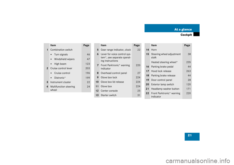
Cockpit
Item
Page
1
Combination switch�
Turn signals
�
Windshield wipers
�
High beam
46
47
123
2
Cruise control lever�
Cruise control
�
Distronic*
203
196
199
3
Instrument cluster
22
4
Multifunction steering
wheel
24
Item
Page
5
Gear range indicator, clock
22
6
Lever for voice control sys-
tem*, see separate operat-
ing instructions
7
Front Parktronic* warning
indicator
220
8
Overhead control panel
27
9
Glove box lock
224
10
Glove box lid release
224
11
Glove box
224
12
Center console
25
13
Starter switch
31
Item
Page
14
Horn
15
Steering wheel adjustment
stalk
Heated steering wheel*
38
235
16
Parking brake pedal
44
17
Hood lock release
263
18
Parking brake release
44
19
Door control panel
28
20
Exterior lamp switch
120
21
Headlamp washer button
171
22
Front Parktronic* warning
indicator
220
Page 23 of 416

23 At a glance
Instrument cluster
Item
Page
1
Coolant temperature
gauge
128
2
Fuel gauge with:Fuel reserve warning lamp
294
3
L
Left turn signal
indicator lamp
K
Right turn signal
indicator lamp
46
4
Speedometer with:v
Electronic Stability
Program (ESP)
warning lamp
l
Distance* warning
lamp
1
1Vehicles without Distronic*: Warning lamp without
function. It illuminates with SmartKey in starter
switch position2. It should go out when the engine
is running.
290
5
Tachometer
129
Item
Page
6
Right display with:-
Antilock Brake Sys-
tem (ABS) malfunc-
tion indicator lamp
290
A
High beam head-
lamp indicator
46
<
Seat belt nonusage
warning lamp
289
7
J
Reset button
127
8
Display with:
Program mode
164
Gear range
indicator
162
Digital clock (see
COMAND operat-
ing instructions)
9
Multifunction display
with:
Trip odometer
130
Main odometer
130
Stored speed for:Cruise control
196
Distronic*
142
10
Outside temperature in-
dicator
129
11
Left display with:1
Supplemental
restraint system
indicator lamp
292
;
Brake warning
lamp, except
Canada
293
3
Brake warning
lamp, Canada only
293
?
Engine malfunction
indicator lamp
294
12
Knob for instrument
cluster illumination
127
Item
Page
Page 127 of 416
.
The instrume")
127 Controls in detail
Instrument cluster
Instrument cluster
A full view illustration of the instrument
cluster can be found in the “At a glance”
section of this manual (
�page 22).
The instrument cluster is activated when
you
�
open a door
�
turn on the ignition
�
press the reset button
J
(�page 22)
�
switch on the exterior lamps
You can change the instrument cluster set-
tings in the Instrument cluster submenu of
the control system (
�page 149).
Instrument cluster illumination
1Knob for adjusting instrument cluster
illumination
Use knob1 to adjust the illumination
brightness for the instrument cluster.
�
Press knob1. The knob will pop out.
To brighten illumination
�
Turn knob1 in the instrument cluster
clockwise.
The instrument cluster illumination will
brighten.
To dim illumination
�
Turn knob1 in the instrument cluster
counterclockwise.
The instrument cluster illumination will
dim.
iThe instrument cluster illumination is
dimmed or brightened automatically to
suit ambient light conditions.
The instrument cluster illumination will
also be adjusted automatically when
you switch on the vehicle’s exterior
lamps.
Page 323 of 416
323 Practical hints
Where will I find ...?
The vehicle tool kit includes:�
One pair of universal pliers
�
Two open-end wrenches
�
One hex-socket wrench
�
One interchangeable slot/Phillips
screwdriver
�
One towing eye bolt
�
One wheel wrench
�
One alignment bolt
�
One fuse extractor
�
One fuse chart for the main fuse box
�
Spare fusesVehicle jack
To prepare the vehicle jack for use
�
Remove the vehicle jack from the spare
wheel well under the trunk floor.
�
Push the crank handle up.
�
Turn the crank handle clockwise until it
engages (operational position).Storing the vehicle jack in the trunk
�
Retract the vehicle jack arm to the
base of the vehicle jack.
�
Push the crank handle up.
�
Turn the crank handle counterclock-
wise to the end of the stop (storage po-
sition).
!To prevent damage, always disengage
trunk floor handle from trunk lid and
lower trunk floor before closing the
trunk lid.
Page 324 of 416

324 Practical hintsWhere will I find ...?
Removing the spare wheel�
Take out the vehicle tool kit tray2.
�
Loosen the luggage bowl3. To do so,
turn the luggage bowl counterclock-
wise
�
Remove the spare wheel4.
Storing the spare wheel
�
Place spare wheel4 in wheel well.
�
Secure the spare wheel. To do so, turn
the luggage bowl3 clockwise to its
stop.
�
Place vehicle tool kit tray2 in luggage
bowl.Spare wheel S 430, S 500 and S 600
(except Sport Package*)
The spare wheel rim is mounted with a full
sized tire of the same type as on the vehi-
cle, and it is fully functional.
However, that spare wheel rim is weight
optimized and has a limited service life of
12 000 miles (20 000 km) use before a
standard wheel rim must replace it.
In case of flat tire, you may temporarily use
the spare wheel.
Do not operate vehicle with more than one
spare wheel mounted.
Warning!
G
The jack is designed exclusively for jacking
up the vehicle at the jack take-up brackets
built into both sides of the vehicle. To help
avoid personal injury, use the jack only to lift
the vehicle during a wheel change. Never
get beneath the vehicle while it is supported
by the jack. Keep hands and feet away from
the area under the lifted vehicle. Always
firmly set parking brake and block wheels
before raising vehicle with jack.
Do not disengage parking brake while the
vehicle is raised. Be certain that the jack is
always vertical (plumb line) when in use, es-
pecially on hills. Always try to use the jack
on level surface. Make sure that the jack
arm is fully seated in the jack take-up brack-
et. Always lower the vehicle onto sufficient
capacity jackstands before working under
the vehicle.
Page 326 of 416
326 Practical hintsUnlocking/locking in an emergency
Unlocking/locking in an emergencyUnlocking the vehicle
Unlocking the driver’s door
If you are unable to unlock the driver’s
door with the SmartKey, open the door
with the mechanical key as follows:
1Mechanical key locking tab
2Mechanical key�
Move locking tab1 in direction of ar-
row and slide the mechanical key2 out
of the housing.
�
Unlock the door with the mechanical
key. To do so, push the mechanical key
into the lock until it stops and turn it
counterclockwise to position1.
iUnlocking your vehicle with the me-
chanical key will trigger the anti-theft
alarm system. To cancel the alarm, do
one of the following:�
Press button
Œ
or
‹
on the
SmartKey.
�
Insert the SmartKey in the starter
switch.
�
If KEYLESS-GO* card present,
press the KEYLESS-GO* start/stop
button (
�page 33).
Page 327 of 416

327 Practical hints
Unlocking/locking in an emergency
Unlocking the trunk
If you are unable to unlock the trunk with
the SmartKey, open the trunk with the me-
chanical key as follows:Trunk lock�
Insert the mechanical key into the
trunk lid lock.
�
Turn the mechanical key counterclock-
wise to position1.
�
Press button2.
The trunk lid swings open.
Locking the vehicle
If you are unable to lock the vehicle with
the SmartKey or the KEYLESS-GO* card,
lock it with the mechanical key as follows:�
Close the passenger doors and the
trunk lid.
�
Press the central locking switch in the
center console (
�page 103).
�
Check to see whether the locking knob
on the passenger door is still visible. If
necessary push it down manually.
�
Lock the driver’s door with the me-
chanical key.
�
Lock the trunk lid if necessary with the
mechanical key (
�page 326).
!The trunk lid swings open upwards au-
tomatically. Always make sure that
there is sufficient overhead clearance.
A minimum height clearance of 6 ft.
(1.85 m) is required to open the trunk
lid.iUnlocking your vehicle with the me-
chanical key will trigger the anti-theft
alarm system. To cancel the alarm, do
one of the following:�
Press button
Œ
or
‹
on the
SmartKey.
�
Insert the SmartKey in the starter
switch.
�
If KEYLESS-GO* card present,
press the start/stop button
(�page 33).
Page 330 of 416
330 Practical hintsOpening/closing in an emergency
Opening/closing in an emergencySliding/pop-up roof
The driving mechanism for the slid-
ing/pop-up roof is located behind the lens
of the interior overhead light.
You can open or close the sliding/pop-up
roof manually should an electrical malfunc-
tion occur.
1Lens
�
Pry off lens1 using a srewdriver.
�
Turn the SmartKey in the starter switch
to position1 or2.
�
Remove the crank from the operator’s
manual pouch.
2Crank
�
Insert crank2 through hole.
�
Turn crank2 clockwise to:�
close slide roof
�
raise roof at the rear
�
Turn crank2 counterclockwise to:�
open slide roof
�
lower roof at the rear
The sliding/pop-up must be resynchro-
nized after being operated manually
(
�page 195).