Page 165 of 360

165 Controls in detail
Driving systems
Rear Park Assist*
The Rear Park Assist system is an electron-
ic aid designed to assist the driver during
parking maneuvers. It visually and audibly
indicates the relative distance between the
rear of the vehicle and an obstacle.
The Rear Park Assist system is automati-
cally activated when you switch on the ig-
nition and shift the gear selector lever to
positionR.The Rear Park Assist system monitors the
rear area of your vehicle by means of four
sensors in the rear bumper.
1SensorsWarning!
G
Rear Park Assist (rear Parktronic) is a sup-
plemental system. It is not intended to, nor
does it replace, the need for extreme care.
The responsibility during parking and other
critical maneuvers always rests with the
driver.
Special attention must be paid to objects
with smooth surfaces or low silhouettes
(e.g. trailer couplings, painted posts, or
street curbs). Such objects may not be de-
tected by the system and can damage the
vehicle.
The operational function of the Rear Park
Assist can be affected by dirty sensors, es-
pecially at times of snow and ice. See
“Cleaning the Rear Park Assist sensors”
(�page 234).
Interference caused by other ultrasonic sig-
nals (e.g. working jackhammers or the air
brakes of trucks) can cause the system to
send erratic indications, and should be tak-
en into consideration.Warning!
G
Make sure that no persons or animals are in
the area in which you are maneuvering. You
could otherwise injure them.
Page 166 of 360

166 Controls in detailDriving systemsRange of the sensors
To function properly, the sensors must be
free of dirt, ice, snow and slush. Clean the
sensors regularly, being careful not to
scratch or damage them.Minimum distance
The minimum distance between the sen-
sors and an obstacle is approximately
20 in (50 cm). If you encounter an obstacle
in this range, all the warning lamps light up
and you hear a warning signal. If the obsta-
cle is closer than the minimum distance,
the actual distance may no longer be indi-
cated by the system.
Center
approx. 59.1 in (150 cm)
Corners
approx. 40 in (100 cm)
!During parking maneuvers, pay special
attention to objects located above or
below the height of the sensors (e.g.
planters or trailer hitches). The Rear
Park Assist system will not detect such
objects at close range and damage to
your vehicle or the object may result.
Ultrasonic signals from outside sourc-
es (e.g. truck air brakes or jackham-
mers) may impair the operation of the
Rear Park Assist system.
Page 301 of 360

301 Practical hints
Towing the vehicle
Transporting the vehicle
When transporting the vehicle, you can use
the towing eyes for pulling the vehicle onto
a trailer or transporter. �
Move the gear selector lever to posi-
tion N.
�
Shift the transfer case to neutral posi-
tion N.
�
To avoid damaging the vehicle, it
should only be tied down on the
wheels / wheel rims, not on chassis
components such as the transverse
link or trailing arm.
Towing the vehicle with various faults�
Comply with all towing information
(�page 299).
I n c a s e o f e n g i n e d a m a g e , t r a n s m i s s i o n
damage or malfunctions in electrical
equipment
�
Move the gear selector lever to posi-
tion N.
�
Shift the transfer case to neutral posi-
tion N.In case of transfer case damage or for
towing vehicle distances exceeding
30 miles (50 km)
The propeller shafts to the drive axles must
be removed.
In case of front axle damage
Raise the front axle when towing. The pro-
peller shaft between the rear axle and the
transfer case must be removed.
In case of rear axle damage
When the rear axle is raised, the vehicle
can only be towed with a wheel lift or a dol-
ly placed under its front wheels.!When removing drive shaft, place M10
nuts on bolts as distance sleeves and
tighten using M8 nuts.
Always install new self-locking nuts
when reinstalling the drive shaft.
Page 302 of 360
302 Practical hintsTowing the vehicleFront towing eye
In the front, the towing eye is located on
the driver’s side under the bumper.
1Towing eye
Rear towing eye
In the rear, the towing eye is located on the
driver’s side under the bumper.
1Towing eye
Freeing a stranded vehicle
Freeing a stranded vehicle, on which the
wheels are dug into sand or mud, should
be done with the greatest of care, especial-
ly if the vehicle is heavily loaded.
Avoid pulling the vehicle jerkily or diago-
nally, since it could result in damage to the
chassis alignment.
Never try to free a vehicle that is still cou-
pled to a trailer.
If possible, a vehicle equipped with trailer
hitch receiver should be pulled backward
in its own previously made tracks.
Page 315 of 360

315 Technical data
Main dimensions, vehicle weights and ratings
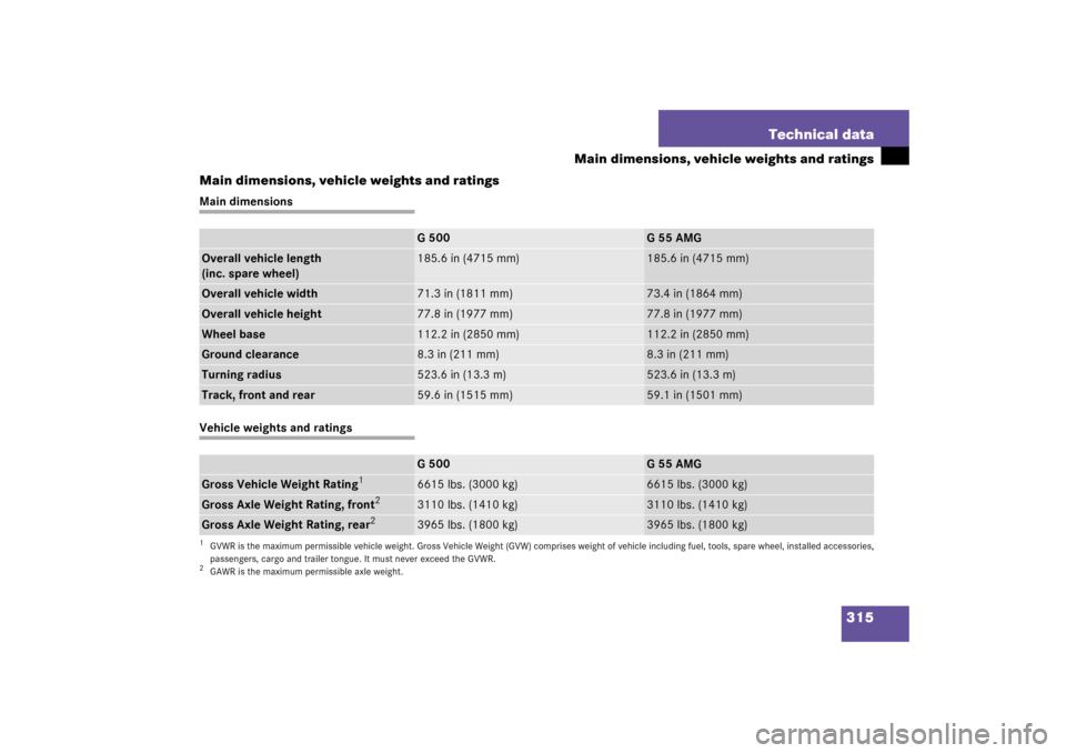
Main dimensions, vehicle weights and ratings
Main dimensionsVehicle weights and ratings
G500
G55AMG
Overall vehicle length
(inc. spare wheel)
185.6 in (4715 mm)
185.6 in (4715 mm)
Overall vehicle width
71.3 in (1811 mm)
73.4 in (1864 mm)
Overall vehicle height
77.8 in (1977 mm)
77.8 in (1977 mm)
Wheel base
112.2 in (2850 mm)
112.2 in (2850 mm)
Ground clearance
8.3 in (211 mm)
8.3 in (211 mm)
Turning radius
523.6 in (13.3 m)
523.6 in (13.3 m)
Track, front and rear
59.6 in (1515 mm)
59.1 in (1501 mm)
G500
G55AMG
Gross Vehicle Weight Rating
1
1GVWR is the maximum permissible vehicle weight. Gross Vehicle Weight (GVW) comprises weight of vehicle including fuel, tools, spare wheel, installed accessories,
passengers, cargo and trailer tongue. It must never exceed the GVWR.
6615 lbs. (3000 kg)
6615 lbs. (3000 kg)
Gross Axle Weight Rating, front
2
2GAWR is the maximum permissible axle weight.
3110 lbs. (1410 kg)
3110 lbs. (1410 kg)
Gross Axle Weight Rating, rear
2
3965 lbs. (1800 kg)
3965 lbs. (1800 kg)