2003 MERCEDES-BENZ E320 WAGON turn signal
[x] Cancel search: turn signalPage 186 of 354
183 Garage door opener
Te ch n i c a l
data Instruments
and controlsOperationDrivingInstrument
cluster displayPractical hints Car care Index Operation of remote control:
1. Turn electronic key in steering lock to position 1
or 2.
2. Select and press the appropriate button to activate
the remote controlled device. The integrated remote
control transmitter continues to send the signal as
long as the button is pressed – up to 20 seconds.Erasing the remote control memory:
1. Turn electronic key in steering lock to position 1
or 2.
2. Simultaneously holding down the left and right side
buttons for approximately 20 seconds, or until the
control lamp blinks rapidly, will erase the codes of
all three channels.
Page 191 of 354
188 Tele Aid
Te ch n i c a l
data Instruments
and controlsOperationDrivingInstrument
cluster displayPractical hints Car care Index
Te l e A i d (optional for Canada)
Important!
The initial activation of the Tele Aid system may only be
performed by completing the subscriber agreement and
placing an acquaintance call using the SOS button.
Failure to complete either of these steps will result in a
system that is not activated. If the system is not
activated the indicator lamp in the SOS button stays on
after turning electronic key in steering lock to position 2
and the message “TELE AID – NOT ACTIVATED” will be
shown in the multifunction display for approx.
10 seconds.
If you have any questions regarding activation, please
call the Response Center at 1-800-756-9018 (in the USA)
or 1-888-923-8367 (in Canada).
(Te l ematic Alarm Identification on Demand)
The Tele Aid system consists of three types of response;
automatic and manual emergency, roadside assistance
and information.The Tele Aid system is operational providing that the
vehicle’s battery is charged, properly connected, not
damaged and cellular and GPS coverage is available.
The speaker volume of a Tele Aid call can be adjusted
when using the volume control on the multifunction
steering wheel, for raising press buttonæ and for
lowering press buttonç.
To activate, press the SOS button, the Roadside
Assistance button• or the Information button¡,
depending on the type of response required.
Shortly after the completion of your Acquaintance Call,
you will receive a user ID and password via first call
mail. By visiting www.mbusa.com and selecting
“Tele Aid” (USA only), you will have access to account
information, remote door unlock, profile and more.
Important!
Tele Aid utilizes the cellular network for
communication and the GPS (Global Positioning
System) satellites for vehicle location. If either of these
signals are unavailable, the Tele Aid system may not
function and if this occurs, assistance must be
summoned by other means.
Page 195 of 354
192 Tele Aid
Te ch n i c a l
data Instruments
and controlsOperationDrivingInstrument
cluster displayPractical hints Car care Index
Roadside Assistance button •
Located below the center armrest cover is the Roadside
Assistance button•. Pressing and holding the
button (for longer than 2 seconds) will initiate a call to a
Mercedes-Benz Roadside Assistance dispatcher. The
button will flash while the call is in progress. The
message “ROADSIDE ASSISTANCE – CONNECTING
CALL” will appear in the multifunction display. When
the connection is established, the message “ROADSIDE
ASSISTANCE – CALL CONNECTED” appears in the
multifunction display. The Tele Aid system will transmit
data generating the vehicle identification number,
model, color and location (subject to availability of
cellular and GPS signals).
A voice connection between the Roadside Assistance
dispatcher and the occupants of the vehicle will be
established. When a voice connection is established the
audio system mutes and the message “TELE AID –
ROADSIDE ASSISTANCE CALL ACTIVE” appears in the
multifunction display. The nature of the need for
assistance can then be described. The Mercedes-Benz
Roadside assistance dispatcher will either dispatch a
qualified Mercedes-Benz technician or arrange to tow
your vehicle to the nearest Mercedes-Benz Center. For services such as labor and/or towing charges may
apply. Refer to the Roadside Assistance manual for more
information.
These programs are only available in the USA:
•Sign and Drive services: Services such as jump start,
a few gallons of fuel or the replacement of a flat tire
with the vehicle spare tire are obtainable,
•Remote Vehicle Diagnostics: This function permits
the Mercedes-Benz Roadside Assistance dispatcher
to download malfunction codes and actual vehicle
data.
Notes:
The indicator lamp in the Roadside Assistance
button• remains illuminated in red for approx.
10 seconds during the system self-check after turning
electronic key in steering lock to position 2 (together
with the SOS button and the Information button¡).
See system self-check on page 189 when the indicator
lamp does not light up in red or stays on longer than
approximately 10 seconds.
Page 196 of 354

193 Tele Aid
Te ch n i c a l
data Instruments
and controlsOperationDrivingInstrument
cluster displayPractical hints Car care Index If the indicator lamp in the Roadside Assistance
button• is illuminated continuously and there was
no voice connection to the Response Center established,
then the Tele Aid system could not initiate an Roadside
Assistance call (e.g. the relevant cellular phone network
is not available). The message “ROADSIDE
ASSISTANCE – CALL FAILED” appears in the
multifunction display.
Roadside Assistance calls can be terminated using the
ìbutton on the multifunction steering wheel.
Information button ¡
Located below the center armrest cover is the
Information button¡. Pressing and holding the
button (for longer than 2 seconds) will initiate a call to
the Customer Assistance Center. The button will flash
while the call is in progress. The message “INFO –
CONNECTING CALL” will appear in the multifunction
display. When the connection is established, the
message “INFO – CALL CONNECTED” appears in the
multifunction display. The Tele Aid system will transmit
data generating the vehicle identification number,
model, color and location (subject to availability of
cellular and GPS signals).A voice connection between the Customer Assistance
Center representative and the occupants of the vehicle
will be established. When a voice connection is
established the audio system mutes and the message
“TELE AID – INFO CALL ACTIVE” appears in the
multifunction display. Information regarding the
operation of your vehicle, the nearest Mercedes-Benz
Center or Mercedes-Benz USA products and services is
ava i l ab le to yo u .
For more details concerning Tele Aid, please visit
www.mbusa.com and use your ID and password, sent to
you separately, to learn more (USA only).
Notes:
The indicator lamp in the Information button¡
remains illuminated in red for approximately
10 seconds during the system self-check after turning
electronic key in steering lock to position 2 (together
with the SOS button and the Roadside Assistance
button•).
See system self-check on page 189 when the indicator
lamp does not light up in red or stays on longer than
approximately 10 seconds.
Page 243 of 354
240 What you should know at the gas station
Te ch n i c a l
data Instruments
and controlsOperationDrivingInstrument
cluster displayPractical hints Car care Index
Fuel tank capacity approximately 21.1 US gal (80.0 l).
This includes approximately 2.6 US gal (10.0 l) reserve.
Use premium unleaded gasoline:
Posted Octane Index 91 (Average of 96 RON / 86 MON).
Engine oil
Engine oil level check, see page 273.
Fill quantity between upper and lower dipstick marking
level: 2.1 US qt (2.0 l).
Recommended engine oils, see Approved Service
Products sheet.
Coolant
For normal replenishing, use water (potable water
quality).
For further information (e.g. anticorrosion /antifreeze),
see page 332.
Spark plugs
Approved spark plugs, see page 326.Tire pressure
For tire pressure, refer to tire pressure label inside the
fuel filler flap.
Air conditioner
R-134a refrigerant and special PAG lubricant, see
page 328.
Bulbs
High and low beams: H7 (55 W),
low beam: Xenon (optional)
fog lamps: H1 (55 W),
turn signal lamps,
front 1156 NA (26.9 / 5 W / 32 / 4 cp),
parking and standing lamps, front: H 6W (6 W)
side marker lamps, front: 5 W / 4 cp,
turn signal lamps, rear: 21 W / 24 cp,
stop, tail and parking lamp: 21 W / 4 cp,
tail, parking and side marker lamp: 5 W / 4 cp,
rear fog lamp, driver’s side: 21 W / 32 cp,
backup lamps: 21 W / 32 cp,
license plate lamps: 5 W / 4 cp
Page 247 of 354
244 Malfunction and indicator lamps
Te ch n i c a l
data Instruments
and controlsOperation DrivingInstrument
cluster displayPractical hints Car care Index
Malfunction and indicator lamps
in the instrument cluster
General information:
If a bulb in the instrument cluster fails to light up
during the bulb self-check when turning the electronic
key in steering lock to position 2, have it checked and
replaced if necessary.
On-board diagnostic system
Check engine malfunction indicator lamp
Engine malfunction indicator lamp. If the
“CHECK ENGINE” malfunction indicator
lamp comes on when the engine is running,
it indicates a malfunction of the fuel management
system, emission control system, systems which impact
emissions, or the fuel cap is not closed tight (check the
fuel cap). If the “CHECK ENGINE” lamp is illuminated
continuously and the vehicle is driving normally, you
may still drive the vehicle, however, in all cases, we
recommend that you have the system checked at your
authorized Mercedes-Benz Center as soon as possible. If the “CHECK ENGINE” lamp comes on continuously
and / or the vehicle is not driving normally, serious
damage can occur to the emission system. Please
contact your authorized Mercedes-Benz Center
immediately.
The Sequential Multiport Fuel Injection (SFI) control
module monitors emission control components that
either provide input signals to or receive output signals
from the control module. Malfunctions resulting from
interruptions or failure of any of these components are
indicated by the “CHECK ENGINE” malfunction
indicator lamp in the instrument cluster and are
simultaneously stored in the SFI control module.
If the “CHECK ENGINE” malfunction indicator lamp
comes on, have the system checked at your authorized
Mercedes-Benz Center as soon as possible.
With some exceptions, the control module switches off
the “CHECK ENGINE” malfunction indicator lamp if the
condition, causing the lamp to come on, no longer exists
during three consecutive cycles. See also page 246 for
fuel cap placement warning.
CHECK
ENGINE
Page 298 of 354
295 Towing the vehicle
Te ch n i c a l
data Instruments
and controlsOperation DrivingInstrument
cluster displayPractical hintsCar care Index 4MATIC: disconnected at the front and rear axle drive
flanges) for any towing beyond a short tow to a nearby
garage.
Important!
When towing the vehicle with all wheels on the ground,
please note the following:
With the automatic central locking activated and the
electronic key in steering lock position 2, the vehicle
doors lock if the left front wheel as well as the right rear
wheel are turning at vehicle speeds of approx. 9 mph
(15 km/h) or more. To prevent the vehicle doors from
locking, deactivate the automatic central locking, see
page 35.
Note:
To signal turns while being towed with hazard warning
flasher in use, turn electronic key in steering lock to
position 2 and activate combination switch for left or
right turn signal in usual manner – only the selected
turn signal will operate.
Upon canceling the turn signal, the hazard warning
flasher will operate again.
Wa r n i n g !
If circumstances require towing the vehicle with
all wheels on the ground, always tow with a tow bar
if:
• the engine will not run
• there is malfunction in the power supply or in
the vehicle’s electrical system
as that will be necessary to adequately control the
towed vehicle.
Prior to towing the vehicle with all wheels on the
ground, make certain that the electronic key is in
steering lock position 2.If the key is left in the steering lock position 0 for
an extended period of time, it can no longer be
turned in the lock. In this case, the steering is
locked. To unlock, remove electronic key from
steering lock and reinsert.Wa r n i n g !
With the engine not running, there is no power
assistance for the braking and steering systems. In
this case, it is important to keep in mind that a
considerably higher degree of effort is necessary to
brake and steer the vehicle.
Page 301 of 354
298 Exterior lamps
Te ch n i c a l
data Instruments
and controlsOperation DrivingInstrument
cluster displayPractical hintsCar care Index
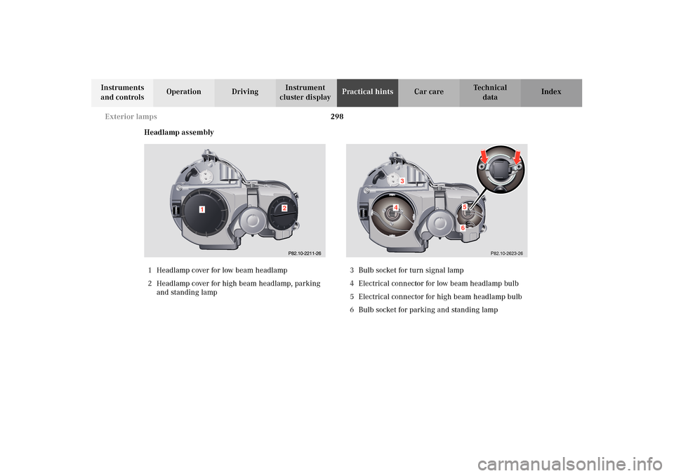
Headlamp assembly
1Headlamp cover for low beam headlamp
2Headlamp cover for high beam headlamp, parking
and standing lamp3Bulb socket for turn signal lamp
4Electrical connector for low beam headlamp bulb
5Electrical connector for high beam headlamp bulb
6Bulb socket for parking and standing lamp
1
2
P82.10-2623-26
143
1156