2003 MERCEDES-BENZ E320 4MATIC WAGON towing
[x] Cancel search: towingPage 7 of 354

4 Contents
BRAKE FLUID .............................254
PARKING BRAKE .......................255
ENGINE FAN ...............................255
COOLANT (coolant level) ..........256
COOLANT TEMP. ........................257
LIGHTING SYSTEM ....................258
LIGHT SENSOR ...........................259
REMOVE KEY .............................259
STEERING GEAR OIL .................260
ENGINE OIL LEVEL ................... 261
WASHER FLUID ..........................262
ELEC. STABIL. PROG. (Electronic
stability program) ......................263
TELE AID .....................................263
Practical hintsFirst aid kit .....................................266
Fuses ................................................267
Electrical outlet ..............................269
Hood .................................................270
Checking engine oil level .............273
Automatic transmission fluid
level ............................................. 274Coolant level ....................................274
Adding coolant ........................... 275
Windshield and headlamp washer
system .........................................276
Windshield and headlamp washer
fluid mixing ratio .......................276
Spare wheel, vehicle tools, storage
compartment ............................. 277
Vehicle jack .................................... 278
Wheels ............................................ 279
Tire replacement ....................... 279
Rotating wheels ......................... 280
Spare wheel .................................... 281
Spare wheel bolts ...................... 281
Changing wheels ........................... 282
Tire inflation pressure ................. 287
Battery ............................................. 289
Jump starting ................................. 291
Towing the vehicle ........................ 294
Transmission selector lever,
manually unlocking ................. 296
Exterior lamps ............................... 297
Headlamp assembly .................. 298
Taillamp assemblies .................. 301Changing batteries in the
electronic key ............................304
Synchronizing remote control .306
Emergency engine shut-down .....306
Emergency operation of sliding /
pop-up roof .................................307
Manual release for fuel
filler flap ....................................308
Replacing wiper blade insert .......308
Roof rack ..........................................311
Vehicle careCleaning and care of the vehicle . 314
Power washer .............................. 315
Tar stains ..................................... 315
Paintwork, painted body
components ................................. 315
Engine cleaning .......................... 316
Vehicle washing ......................... 316
Ornamental moldings ................ 316
Headlamps, taillamps, turn signal
lenses ........................................... 316
Cleaning the parktronic system
sensors ......................................... 317
Page 38 of 354
35 Central locking system
Te ch n i c a l
data Instruments
and controlsOperationDrivingInstrument
cluster displayPractical hints Car care Index Automatic central locking
The central locking switch also operates the automatic
central locking.
With the automatic central locking system activated, the
doors and trunk are locked at vehicle speeds of
approximately 9 mph (15 km / h) or more. The fuel filler
flap remains unlocked.
To a c ti va te :
With electronic key in steering lock position 2 hold
upper portion of switch (1) for a minimum of 5 seconds.
To d ea ct iva te:
With electronic key in steering lock position 2 hold
lower portion of switch (2) for a minimum of 5 seconds.
Notes:
If doors are unlocked with the central locking switch
after activating the automatic central locking, and
neither door is opened, then the doors remain unlocked
even at vehicle speeds of approximately 9 mph
(15 km / h) or more.If a door is opened from the inside at speeds of
approximately 9 mph (15 km / h) or less with the
automatic central locking activated, the door will again
be automatically locked at speeds of approximately
9mph (15km/h) or more.
Important!
When towing the vehicle, or with the vehicle on a
dynamometer test stand, please, note the following:
With the automatic central locking activated and the
electronic key in steering lock position 2, the vehicle
doors will lock if the left front wheel as well as the right
rear wheel spin at vehicle speeds of approximately
9mph (15km/h) or more.
To prevent the vehicle door locks from locking,
deactivate the automatic central locking.
Emergency unlocking in case of accident
The doors unlock automatically a short time after a
strong deceleration is detected, such as in a collision
(this is intended to aid rescue and exit).
Driving on rough roads may cause the vehicle to unlock.
If necessary, the vehicle can be locked again with the
central locking switch, see page 34.
Page 165 of 354
162 Interior equipment
Te ch n i c a l
data Instruments
and controlsOperationDrivingInstrument
cluster displayPractical hints Car care Index
Interior
Armrest, rear bench
Pull down the armrest by its top.Cup holder in rear bench armrest
Press button and pull out drawer to its detent.
Caution!
Keep cup holder closed while traveling. Place only
containers that fit into the cup holder to prevent spills.
Do not fill containers to a height where the contents
could spill during vehicle maneuvers, especially hot
liquids.
Wa r n i n g
To help avoid personal injury during a collision or
sudden maneuver, exercise care when stowing
things. Put luggage or cargo in the trunk if
possible. Do not pile luggage or cargo higher than
the seat backs. Do not place anything on the shelf
below the rear window.Luggage nets cannot secure hard or heavy objects.
P91.27-2005-26
Page 195 of 354
192 Tele Aid
Te ch n i c a l
data Instruments
and controlsOperationDrivingInstrument
cluster displayPractical hints Car care Index
Roadside Assistance button •
Located below the center armrest cover is the Roadside
Assistance button•. Pressing and holding the
button (for longer than 2 seconds) will initiate a call to a
Mercedes-Benz Roadside Assistance dispatcher. The
button will flash while the call is in progress. The
message “ROADSIDE ASSISTANCE – CONNECTING
CALL” will appear in the multifunction display. When
the connection is established, the message “ROADSIDE
ASSISTANCE – CALL CONNECTED” appears in the
multifunction display. The Tele Aid system will transmit
data generating the vehicle identification number,
model, color and location (subject to availability of
cellular and GPS signals).
A voice connection between the Roadside Assistance
dispatcher and the occupants of the vehicle will be
established. When a voice connection is established the
audio system mutes and the message “TELE AID –
ROADSIDE ASSISTANCE CALL ACTIVE” appears in the
multifunction display. The nature of the need for
assistance can then be described. The Mercedes-Benz
Roadside assistance dispatcher will either dispatch a
qualified Mercedes-Benz technician or arrange to tow
your vehicle to the nearest Mercedes-Benz Center. For services such as labor and/or towing charges may
apply. Refer to the Roadside Assistance manual for more
information.
These programs are only available in the USA:
•Sign and Drive services: Services such as jump start,
a few gallons of fuel or the replacement of a flat tire
with the vehicle spare tire are obtainable,
•Remote Vehicle Diagnostics: This function permits
the Mercedes-Benz Roadside Assistance dispatcher
to download malfunction codes and actual vehicle
data.
Notes:
The indicator lamp in the Roadside Assistance
button• remains illuminated in red for approx.
10 seconds during the system self-check after turning
electronic key in steering lock to position 2 (together
with the SOS button and the Information button¡).
See system self-check on page 189 when the indicator
lamp does not light up in red or stays on longer than
approximately 10 seconds.
Page 268 of 354
265 Contents – Practical hints
Te ch n i c a l
data Instruments
and controlsOperation DrivingInstrument
cluster displayPractical hintsCar care Index
Practical hintsFirst aid kit .....................................266
Fuses ................................................267
Electrical outlet ..............................269
Hood .................................................270
Checking engine oil level .............273
Automatic transmission fluid
level ............................................. 274
Coolant level ................................... 274
Adding coolant ...........................275
Windshield and headlamp washer
system ......................................... 276
Windshield and headlamp washer
fluid mixing ratio ....................... 276Spare wheel, vehicle tools, storage
compartment ............................. 277
Vehicle jack .................................... 278
Wheels ............................................ 279
Tire replacement ....................... 279
Rotating wheels ......................... 280
Spare wheel .................................... 281
Spare wheel bolts ...................... 281
Changing wheels ........................... 282
Tire inflation pressure ................. 287
Battery ............................................. 289
Jump starting ................................. 291
Towing the vehicle ........................ 294
Transmission selector lever,
manually unlocking ................. 296Exterior lamps ................................297
Headlamp assembly ...................298
Taillamp assemblies .................. 301
Changing batteries in the
electronic key ............................304
Synchronizing remote control .306
Emergency engine shut-down .....306
Emergency operation of sliding /
pop-up roof .................................307
Manual release for fuel
filler flap ....................................308
Replacing wiper blade insert .......308
Roof rack ..........................................311
Page 297 of 354
294 Towing the vehicle
Te ch n i c a l
data Instruments
and controlsOperation DrivingInstrument
cluster displayPractical hintsCar care Index
Tow i n g t h e ve h i c l e
Mercedes-Benz recommends that the vehicle be
transported with all wheels off the ground using flatbed
or appropriate wheel lift/ dolly equipment. This method
is preferable to other types of towing.
Caution!
Use flatbed or wheel lift/ dolly equipment with key in
steering lock turned to position 0.
Do not tow with sling- type equipment. Towing with
sling- type equipment over bumpy roads will damage
radiator and supports.
To prevent damage during transport, do not tie down
vehicle by its chassis or suspension parts.
Switch off the tow-away alarm (see page 41) as well as
the ESP (see page 232).
When circumstances do not permit the recommended
towing methods, the vehicle may be towed with all
wheels on the ground or front wheels raised only so far
as necessary to have the vehicle moved to a safe location
where the recommended towing methods can be
employed.Caution!
Ve h i c l e s w i t h 4 M AT I C :
Do not tow with one axle raised. Doing so could damage
the transfer case, which is not covered by the Mercedes-
Benz Limited Warranty.
Caution!
If the vehicle is towed with the front axle raised (not
permissible for vehicles with 4MATIC), the engine must
be shut off (electronic key in steering lock in position 0
or 1). Otherwise, the EPS will immediately be engaged
and will apply the rear wheel brakes.
When towing the vehicle with all wheels on the ground,
the selector lever must be in position “N” and the key
must be in steering lock po sition 2.
When towing the vehicle with all wheels on the ground
or the front axle raised, the vehicle may be towed only
for distances up to 30 miles (50 km) and at a speed not
to exceed 30 mph (50 km/h).
To be certain to avoid a possibility of damage to the
drivetrain, however, we recommend the drive shaft be
disconnected at the rear axle drive flange (vehicles with
Page 298 of 354
295 Towing the vehicle
Te ch n i c a l
data Instruments
and controlsOperation DrivingInstrument
cluster displayPractical hintsCar care Index 4MATIC: disconnected at the front and rear axle drive
flanges) for any towing beyond a short tow to a nearby
garage.
Important!
When towing the vehicle with all wheels on the ground,
please note the following:
With the automatic central locking activated and the
electronic key in steering lock position 2, the vehicle
doors lock if the left front wheel as well as the right rear
wheel are turning at vehicle speeds of approx. 9 mph
(15 km/h) or more. To prevent the vehicle doors from
locking, deactivate the automatic central locking, see
page 35.
Note:
To signal turns while being towed with hazard warning
flasher in use, turn electronic key in steering lock to
position 2 and activate combination switch for left or
right turn signal in usual manner – only the selected
turn signal will operate.
Upon canceling the turn signal, the hazard warning
flasher will operate again.
Wa r n i n g !
If circumstances require towing the vehicle with
all wheels on the ground, always tow with a tow bar
if:
• the engine will not run
• there is malfunction in the power supply or in
the vehicle’s electrical system
as that will be necessary to adequately control the
towed vehicle.
Prior to towing the vehicle with all wheels on the
ground, make certain that the electronic key is in
steering lock position 2.If the key is left in the steering lock position 0 for
an extended period of time, it can no longer be
turned in the lock. In this case, the steering is
locked. To unlock, remove electronic key from
steering lock and reinsert.Wa r n i n g !
With the engine not running, there is no power
assistance for the braking and steering systems. In
this case, it is important to keep in mind that a
considerably higher degree of effort is necessary to
brake and steer the vehicle.
Page 299 of 354
296 Towing the vehicle
Te ch n i c a l
data Instruments
and controlsOperation DrivingInstrument
cluster displayPractical hintsCar care Index
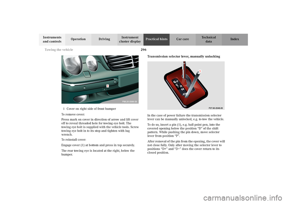
1Cover on right side of front bumper
To remove cover:
Press mark on cover in direction of arrow and lift cover
off to reveal threaded hole for towing eye bolt. The
towing eye bolt is supplied with the vehicle tools. Screw
towing eye bolt in to its stop and tighten with lug
wrench.
To reinstall cover:
Engage cover (1) at bottom and press in top securely.
The rear towing eye is located at the right, below the
bumper.Transmission selector lever, manually unlocking
In the case of power failure the transmission selector
lever can be manually unlocked, e.g. to tow the vehicle.
To do so, insert a pin (1), e.g. ball point pen, into the
covered opening below the position “D” of the shift
pattern. While pushing the pin down, move selector
lever from position “P”.
After removal of the pin from the opening, the cover will
not close fully. Only after moving the selector lever to
positions “D+” and “D–” does the cover return to its
closed position.